Water treatment, Power supply, Power wiring – Carrier 30GA User Manual
Page 3: Table 4 — electrical data
Attention! The text in this document has been recognized automatically. To view the original document, you can use the "Original mode".
$»«je8ER Fl.AN«ED
WASHER
MEORRERE
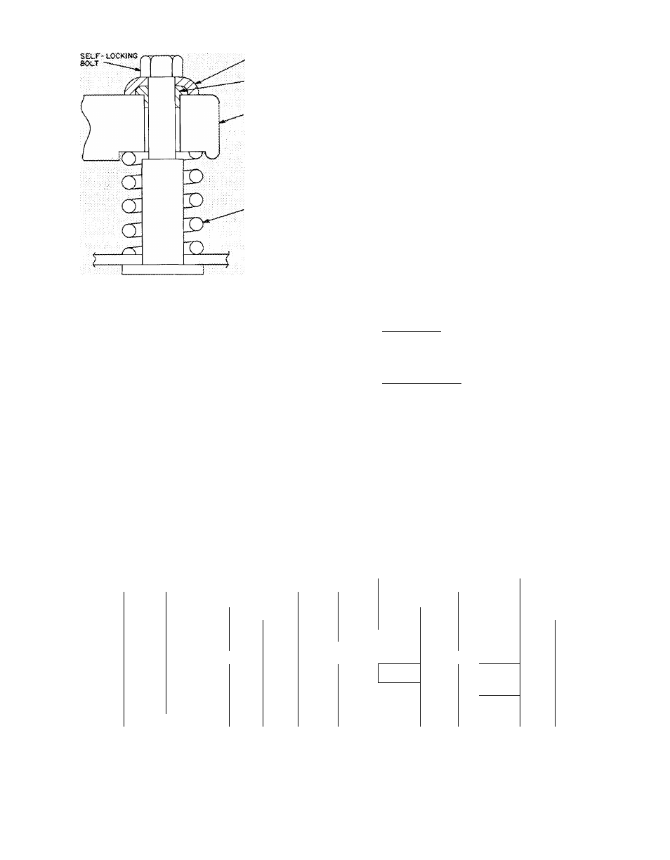
SNUB8ER
. COMPRESSOR POOT
(SOCATJON SPRiNC
Fig. 2 — Compressor Mounting
Chilled Water and Drain Piping
— Facing the cooler
side of the unit, the return water connection is on
the left and the leaving water connection is on the
riglrt (see Fig. 1). The connections are oriented
vertically to minimize pressure losses and to facili
tate field piping for roof-mounted installations. A
means of venting air from the high point of the
field-installed piping should be provided. After
field piping is complete, wrap all piping with elec
tric heating tape and cover with suitable thickness
of closed-cell insulation. The power source for the
electric heating is the 115-volt (60-FIertz only) con
venience outlet in the bottom of the cooler section,
at compressor end. The cooler drain connection is
at compressor end (see Fig. 1). Drain piping can be
installed directly thru hole provided in cooler
section base pan. Insulate this piping, similar to
the chilled water piping, for at least one foot
from cooler.
Water Treatment
— Consult local water authority
on characteristics of water in the area and add a
recommended inliibitor to the chilled water.
Power Supply
~ Electrical characteristics of avail
able power supply must agree with unit nameplate
rating. Supply voltage must be within the limits
shown in Table 4.
IMPORTANT; Operation on improper supply
voltage or with excessive phase unbalance con-
.stitutes abuse and is not covered by Carrier
Warranty,
Power Wiring
— All power wiring must comply
with applicable local and national codes. Install a
field-supplied branch circuit disconnect switch per
NEC of a type that can be locked OFF or OPEN.
FIELD CONNECTIONS
1. Main Power — Bring wires from the disconnect
switch thru hole in bottom of unit control box
(Fig. 1) and connect to terminals LI, L2, L3 on
line side of terminal block TBl (see Fig. 3).
2. Auxiliary Power — Bring separate source power
(115-1-60) into unit as shown in Fig. 1 and Fig. 3.
This supplies power for control circuit, compres
sor crankcase heater, cooler heater and conven
ience outlet for miscellaneous auxiliary 115-volt
applications. Connect incoming wires to TB2 in
unit control box (LI toQ] and L2 to[2]). In the
auxiliary power supply, a field-supplied dis
connect with 15-amp circuit protection must be
provided to take care of crankcase heater and
cooler heater cable.
In compliance with NEC Article 440-14, the dis
connect must be located within sight of and
readily accessible from the unit.
Table 4 — Electrical Data
UNIT
COMPRESSOR
EACi-
V
d
U
s
Max
CCB
“ F
l
30GA
Mode I
Supp lied*
MCA
>"use
RLA
LRA
Fan
Min
Max
P
1 MTA
It
530
208/230
187
253
103
175
.........
76
......
^ 345
~6
S3
4.5
020
630
460
414
508
51
80
36
173
3
DO
1 9
130
575
518
632
41
60
28 6
120
3
1 40
1 6
530
208/230
187
253
145
225
100
446
6
.......
7(Г“
6.2
025
630
460
414
508
69
1 10
48
223
6
3 0
130
575
518
632
61,7
70
4d> .6
164
3
1 oT
2.4
530
208/230
187
253
168
275
\\o
506
6
83
6 2
030
630
460
414
508
72
110
ZiO
253
6
;
35
3 0
130
575
518
632
63 5
80
45
176
3
63
2 4
No.
2.3
4 6
1 9
1 6
6 6
3 0
2 4
6 6
3 0
2.4
CCB
-
FCB
-
FLA
-
LRA
-
MCA -
RLA for each motor winding is half the value shown
MTA shown is for eacli 3-pole section of the CB (each
motor winding)
Compressor Circuit Breaker
Fan Circuit Breaker (one for all fans)
Full Load Amps (fan motors)
Locked Rotor Amps
Minimum
Circuit
Amps
Complies
with
NEC,
Section
430-24
FCB
MTA
29
18
14
29
18
14
29
18
14
MTA — Must Trip Amps (factory-installed circuit breaker)
P — No of poles in CCB
RLA — Rated Load Amps (compressor)
*Units are suitable for use on electrical systems where voltage
supplied to the unit terminals is not below or above the min
and max limits shown
■fAdjacent to compressor compartment (non-cycling)
NOTE
Maximum
allowable
phase
unbalance
is
volts,
2%:
amps, 10%