Fàble*^2 — physical data, Safety considerations, Installation – Carrier 30GA User Manual
Page 2: Table 3 — fastener package, V4 1, 16x1
Attention! The text in this document has been recognized automatically. To view the original document, you can use the "Original mode".
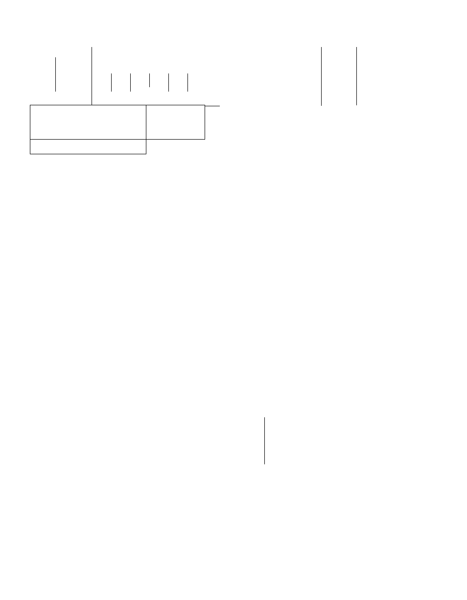
Table 1 — Weight Distribution
"fàble*^2 — Physical Data
UNIT
30GA
020
”
025
030
APPROX
location
UNIT 30 G A
020 ’
OPER WT
(lb)
1.
2
.3 J
J.
.
Weight (lb)
5
6
APPROX NET WT (lb)
REFRIG CHARGE, R-22 (lb)
2600
55
2695
756
190
905
372
2^'2
260
COMPR 06E*
2250
2875
790
200
960
415
235
275
No. Cyl...Rpm
4 Ï 750
3270
830
330
990
540
270
310
14
Propel 1 er.
4
6
Oil Charge (pt)t
COND FANS, Rpm
CONDENSER SECTION
COMPR SECTION
COOLER SECTION
3 5
PLAN VIEW — SUPPORT POINTS
^
SAFETY CONSIDERATIONS
Installation, start-up and servicing of this equip
ment can be hazardous due to system pressures,
electrical components and equipment location
(roofs, elevated structures, etc.).
Only trained, qualified installers and service
mechanics should install, start-up and service this
equipment.
Untrained personnel can perfonn basic main
tenance functions of cleaning coils, cleaning and
replacing filters. All other operations should be
performed by trained service personnel.
When working on the equipment, observe pre
cautions in the literature, tags, stickers and labels
attached to the equipment and to any other
safety precautions that apply.
• Follow all safety codes.
• Wear safety glasses and work gloves.
• Use care in handling, rigging and setting bulky
equipment.
WARNING; Be sure power to equipment
is
shut
off before performing maintenance or service.
INSTALLATION
Rigging
— Preferred method is with spreader bars
from above the unit, utilizing the 4 eyebolts and
washers provided in fastener package (Table 3,
items 4, 5). Otherwise, rig with chains or cables
from above, using the eyebolts. Adjust cable or
chain length so that suspension angle with top of
unit is 45° or greater. If movement with rollers is
required, do not remove the unit from the skid
until it is in final position.
Placing Unit
— Locate so condenser airflow is un
restricted on all sides and on top (see Fig. 1 ).
Provide ample room for servicing cooler For re
moval from compressor end, the 4-ft clearance
shown is sufficient for all units. For removal from
opposite end, see clearance dimension on Fig. 1.
Motor Hp
Total Airflow (cfm)
COND COILS
Rows...Fins/ln.
Total Face Area (sq ft)
COOLER
Max Work. Press, (psig)
RefrIg Side
Water Side
Refrig Circuits
025
2780
57 5
3265
6
V
4
1
18,200 ! 25,200
V Type, Plate
3
124
35 4
I
39
30HR030
235
250
2
030
3175
63
3275
1750
19
irive, 1140
1
28,200
49 6
*N0 of electric unloaders: 2 = one: 3
fSee OH Charge for Carrier approved oil
Erecting Unit
— When unit is in proper location,
attach the 6 legs. Legs are lagged to skid at com
pressor end; screws, lockwashers and nuts are in
fastener package (Table 3, items 1, 2, 3), taped to
unit frame at condenser end. Remove 8 bolts and
2 nuts holding unit to skid and raise unit to remove
skid. Secure legs at 1,2, 3, 4, 5, 6 (Table 1). Three
mounting holes are provided at each of the 6 desig
nated points. Ten of the holes (inside compressor
section) are provided with weld nuts. Loose nuts
are furnished for the other 8 holes. In the bearing
plate at the bottom of each leg is a hole for secur
ing to supporting structure or mounting on vibra
tion isolators if required (see Fig. 1 ). Fasteners for
this mounting must be field supplied.
Table 3 — Fastener Package
TEM
REQ
PER
UNIT
i
Ï8
2
18
3
8
4
4
5
4
6
1
7
1
DESCRIPTION
16x1
Screw, Hex Hd
%
Lockwasher,
%
Nut, Hex % - 16
Eyebolt,
^/2
— 1 3 x 1 in Lg
Washer, SAE
%
Clamp, Tube
Screw, Hex Hd no
8 — 32 x %
Lg
Lg
Compressor Mounting
— As shipped, compressor is
held down by special self-locking bolts and plain
lock washers. After unit is installed, remove the
self-locking bolts one at a time and reassemble with
flanged washers and neoprene snubbers as shown in
Fig. 2. Special flanged washers and neoprene snub
bers are shipped in a cloth bag tied to one of the
compressor feet. Tighten all 4 bolts. Then loosen
each until the flanged washer can be moved side
ways with finger pressure.