Access for servicing (see fig. 5) – Carrier 30GA User Manual
Page 5
Attention! The text in this document has been recognized automatically. To view the original document, you can use the "Original mode".
leaks. After leaks are repaired, the system must be
dehydrated. For leak testing and dehydration pro
cedures, refer to Carrier Standard Service Tech
niques Manual, Chapter 1, Refrigerants, Sections 6
and 7.
Refrigerant Charge
— When additional or complete
field charging is required, refer to Table 1 and use
the Liquid Charging Method. Refer to Carrier
Standard Service Techniques Manual, Chapter 1,
Refrigerants, Section 8, for charging procedures.
Immediately ahead of the filter-drier is a factory-
installed liquid shutoff charging valve. A 1/4-in.
flare connection is provided for field charging.
CAUTION: Never charge liquid in to low-pressure
side of system.
Auxiliary Power Circuit
— Switch 115-1-60 field
disconnect to ON. The cooler heater is factory
wired into the control circuit. Compressor crank
case heater should be on as soon as auxiliary circuit
is energized. Allow crankcase heater to operate at
least 24 hours before starting unit, then close main
power circuit breaker.
Actual Start-Up
should be done only under super
vision of a qualified refrigeration mechanic:
1. Open any compressor and system valves that
were closed during charging.
2. Turn control circuit toggle switch to ON.
3. Push control reset button and chilled water
safety thermostat reset button to ensure circuit
operation.
4. Be sure all safety devices are satisfied.
^ 5. Check to see that the leaving chilled water
temperature agrees with the dial setting on the
temperature controller. If it is not the same as
the dial setting, the variation can be compensated
by shifting the control point slightly to obtain
the proper leaving chilled water temperature.
Access for Servicing (See Fig. 5)
UNIT CONTROL BOX has a gasketed removable
outer cover held on with thumb screws. An inner
panel is hinged and fastened with 2 screws. When
the inner cover is closed, the following components
are accessible; compressor and fan circuit breakers,
control circuit reset buttons, control circuit ON-
OFF switch, water safety thermostat reset button
and chilled water temperature controller set point
adjustment.
COMPRESSOR SECTION Removable top cover
and quick-access side and front panels permit ser
vicing without disturbing the condenser and fans.
In this section are the replaceable-core filter-drier,
liquid line shutoff charging valve, and moisture-
liquid indicator.
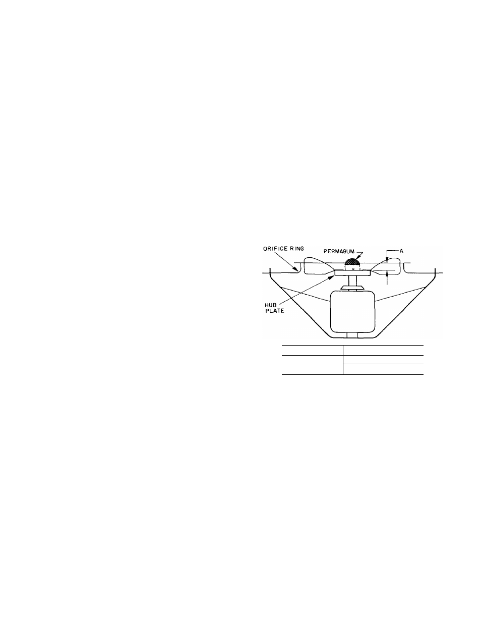
CONDENSER SECTION — Each fan motor is
clamped in a formed-wire mount. Each clamp con
sists of 2 formed-steel straps with 2 sets of bolts,
washers and nuts. The motor mount is supported
from the fan deck. If a fan motor is repaired or re
placed, be sure the wire fan guard is in place over
each fan before starting unit. See Fig. 4 for proper
fan adjustment. Secure fan hub on motor shaft
with 2 setscrews, which bear against the key. Be
sure Permagum is applied to exposed end of motor
shaft to ensure against moisture causing fan to rust
on shaft.
UNIT 3ÒGA
DIMENSION A (in.)
020
025-030
U
/32
;
End Fans
Fig. 4 — Fan Adjustment
COOLER SECTION -- Removable service panels
are provided at each end for general servicing. For
more extensive work on cooler, the full length
cover can be removed. If it is necessary to remove
cooler tubes or cooler, place a support under frame
at point “A” (Fig. 5) at each end and remove (2)
struts. Do not remove supports until the struts are
replaced.
Cooler Head Bolt Tightening
— If the cooler heads
are removed for any reason, use the following
torques and follow the given tightening sequence
when reassembling;
Torques — 5/8-in. diam bolts.......... 150 to 170 Ib-ft
1/2-in. diam bolts,
or nuts................... •......... 70 to 90 Ib—ft