Carrier 30GA User Manual
Page 7
Attention! The text in this document has been recognized automatically. To view the original document, you can use the "Original mode".
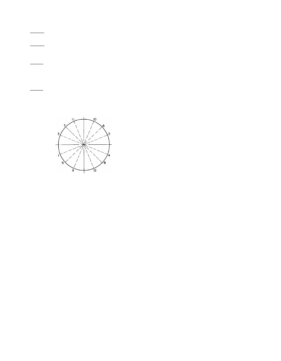
BOLT TIGHTENING SEQUENCE (See Fig. 6)
Step 1 — Tighten moderately (without torquing)
all the flange bolts in the sequence shown.
Step 2 — Tighten moderately (without torquing)
the hex nuts on the center studs (no specified
sequence).
Step 3 — Repeat Step 1, tightening the bolts to the
specified torque.
Step 4 ~ Repeat Step 2, tightening the nuts to the
specified torque.
Step 5 — Not less than one hour later, retighten the
center stud nuts to the specified torque.
TOP
Fig. 6 — Tightening Sequence, Cooler Head Bolts
Oil Charge
— Compressor is factory charged with
oil. Each 30GA020 unit has 14 pints of oil; each
30GA025 and 030 unit has 19 pints. When addi
tional oil or a complete charge is required, use only
Carrier approved compressor oil
Sun Oil Company..................................... Suniso 3GS
Texaco, Inc................................ Capella WFI-32-150
E.I. DuPont Company...........................Zephron 150
(Synthetic)
IMPORTANT; Do not reuse drained oil or use
oil tiiat has been exposed to atmosphere. Refer
to Cssrrier Standard Sendee Teclmiques Manual,
Chapter 1, Refrigerants for procedures to add or
remove oil.
Thermostatic Expansion Valves,
one for each of
the 2 refrigerant circuits, are factory set to main
tain 6 — 7 F superheat of vapor leaving cooler to
control flow of liquid refrigerant to cooler. Super
heat can be reset but should be done only if abso
lutely necessary. The complete power head and
cage assembly can be removed for servicing with
out removing the body flange from the liquid line.
The thennostatic expansion valves have non
condensable-charge power elements.
-^Liquid Line Solenoid Valves,
one in each of the
2 refrigerant circuits, are interlocked with the
water temperature controller to shut off the flow
of refrigerant to the cooler when the water temper
ature controller (WTC) call for cooling is satisfied.
They are located immediately upstream of the
thermostatic expansion valves. With single pumpout
control, the compressor continues to run after the
WTC is satisfied and the refrigerant flow is shut off
Tliis causes pumpout of refrigerant from the cooler
and subsequent shutdown of the compressor on
low-pressure control. The compressor will not
restart until the WTC again calls for cooling.
Discharge Line Check Valve
— A check valve in the
compressor discharge line prevents migration of
refrigerant from the condenser to the compressor
during the off cycle.
Moisture-Liquid Indicator
— Clear flow of liquid
refrigerant indicates sufficient charge in system.
Bubbles indicate undercharged system or presence
of noncondensables. Moisture, measured in parts
per million (ppm), in system changes color of indi
cator. Green — moisture is below 45 ppm, char
treuse (caution) — 45 to 130, yellow (wet) — above
130. Change filter-drier cores at first sign of mois
ture in system.
IMPORTANT: Unit musí be m operation at
least 12 hours before moisture indicator can give
an accurate reading. With unit running, indicat
ing element mxist be in contact with liquid
reirigexant to give true moisture indication.
Filter-Drier
— Whenever the moisture-liquid indi
cator shows presence of moisture, replace filter-
drier core. Refer to Carrier Standard Service Tech
niques Manual, Chapter 1, Refrigerants for details
on servicing filter-driers.
Liquid Shutoff/Charging Valve
is located imme
diately ahead of filter-drier, provided with 1/4-in.
flare connection for field charging.
Compressor Protection
CIRCUIT BREAKER — Calibrated trip manual
reset, magnetic. Protects against motor overload
and locked rotor conditions.
THERMAL PROTECTOR - A sensor in the dis
charge side of the compressor reacts to excessively
high discharge temperature and shuts off the com
pressor. The high discharge temperature indicates
overtemperature in the compressor motor.
TIME GUARD® function protects compressor
against short cycling. See Sequence of Control.