Operation, Fig. 9 — timer cycle, Sequence of control – Carrier 30GA User Manual
Page 10
Attention! The text in this document has been recognized automatically. To view the original document, you can use the "Original mode".
tion and allow the unit to run thru a cycle. At the
instant the last step of capacity unloads (switch
no. 1 opens), read the temperature. If it is not the
same as the dial reading, the variation can be com
pensated by shifting the control point sliglrtly.
C'AUTION: Do not force tlie dial pasit the stop.
'Hus could cause loss of the control point and
dajnage the instrument,
HOT GAS BYPASS VALVE modulates flow of hot
gas into no. 1 refrigerant circuit in response to vari
ations from preset suction pressure. A sudden de
crease in suction pressure causes valve to admit
more hot gas to restore the preset pressure level.
The hot gas enters the refrigerant circuit thru the
connecting tube between the thermal expansion
valve and the cooler. With hot gas bypass, the 30GA
units operate down to a lower load condition; the
result is less off-on cycling of the chiller.
The remote pressure sensing tubing is factory in
stalled running from a 1/4-in. flare connection in
the power head of the valve to the outlet of no. 1
refrigerant circuit, adjoining the external equalizing
connection for the thermal expansion valve. The
bypass valve is factory set to maintain 66 psig suc
tion pressure. For other than control from return
water temperature thru a 10 F range with 44 F
leaving water temperature, the set point may be
adjusted in the pressure range of 0 ^ 80 psig. One
full turn clockwise of the adjustment stem raises
set pressure approximately 5 psig, and vice versa.
>
OPERATION
Refer to Control Circuit diagram on the unit, or
in the Wiring Diagrams publication.
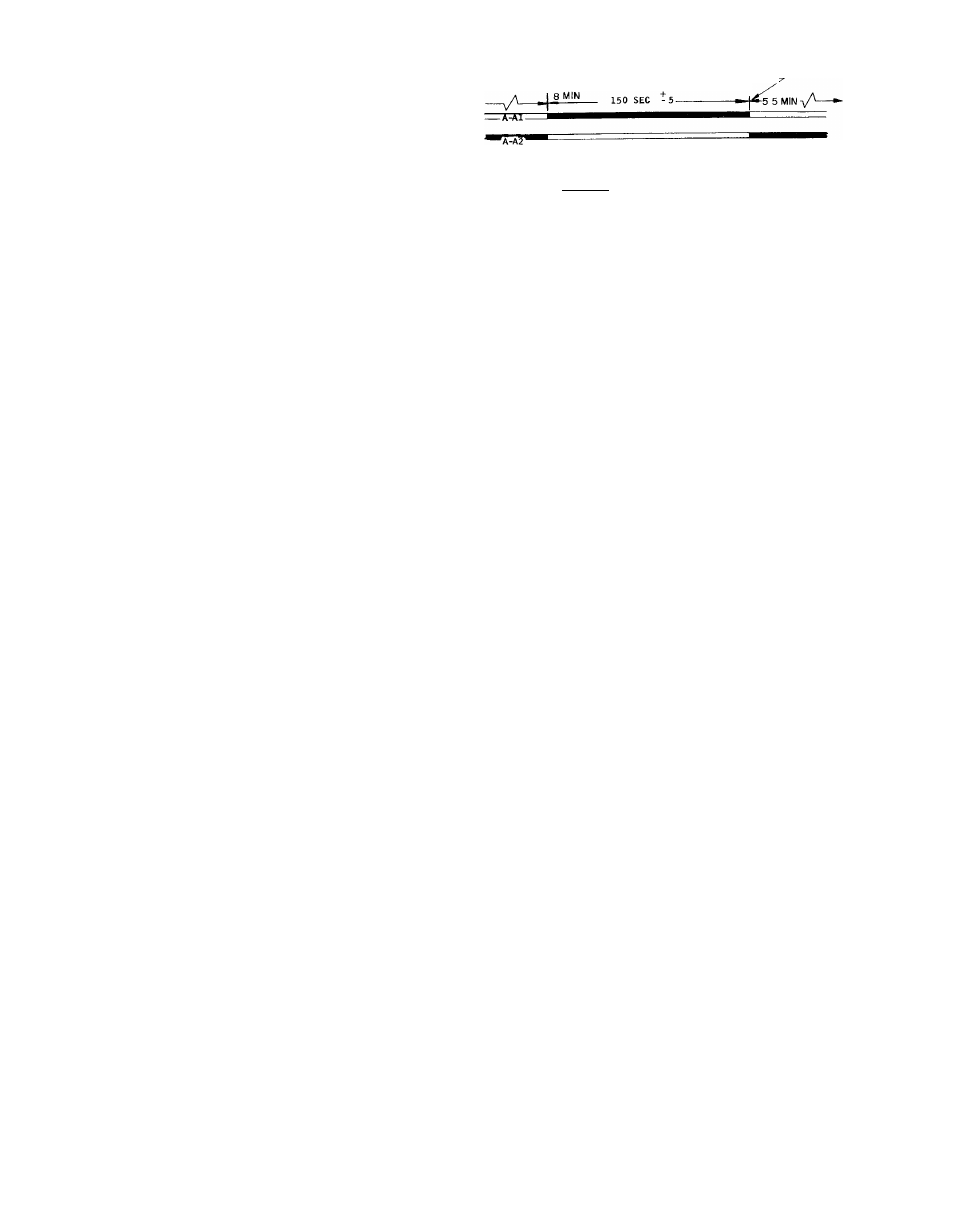
Timer Functions
(See Fig. 9 — Timer Cycle)
1. Switch “A” (contacts A-Al and A-A2) provides
Time Guard® function. Start of compressor is
delayed approximately 5.5 minutes after shut
off. The minimum time between starts of com
pressor is 8 minutes.
2. Switch “B” (contacts B-Bl and B-B2) starts com
pressor and provides one-second time delay for
part-winding start.
3. Switch “D” (contacts D-Dl) bypasses the low-
pressure switch (LPS) for 2.5 minutes at start-up
for winter start control.
(BLACK DENOTES CLOSED CONTACTS) TIMER POSITION DURING
UNIT OPERATION-
0 MIN OR
|_— 12 SEC +2
4—— 1 SEC ± 0.5
|— 5 SEC t2
2-6 SEC
-H h-2-6 SEC
150 SEC - 5
5 5 MIN -
Fig. 9 — Timer Cycle
Sequence of Control
At start-up, with the water temperature con
troller (WTC) calling for cooling and all safety
devices satisfied, the control circuit switch is closed.
With minimal demand for cooling, only the first
WTC switch is made. The timer motor starts, liquid
line solenoid valve no. 1 (LLSl) opens and the con
denser fans start. After a delay by the Time Guard
control of 12 seconds to approximately 8 minutes
depending on the timer position, the compressor
starts, unloaded. As cooling demand increases, the
unit capacity increases as follows:
30GA020 (Two-Step Controller)
The second WTC switch makes and LLS no. 2
opens. The compressor loads and the unit is oper
ating at full capacity.
30GA025, 030 (Three-Step Controller)
The second WTC switch makes: LLS no. 2 opens
and one compressor unloader is de-energized in
creasing the capacity.
The third WTC switch makes: the second com
pressor unloader is de-energized increasing the unit
to full capacity.
A pumpout relay (FOR) in the control circuit is
energized when WTC no. 1 switch makes. A set of
normally open FOR contacts close, completing a
compressor control circuit which bypasses the
WTC switches.
As cooling demand is satisfied, WTC switches
break in descending sequence. The LLS valves close,
stopping the flow of liquid refrigerant to the cooler
and subsequent suction gas to the compressor.
After the last WTC switch breaks, the compressor
continues to run because of the WTC switch bypass.
10