Carrier 58DH User Manual
Page 7
Attention! The text in this document has been recognized automatically. To view the original document, you can use the "Original mode".
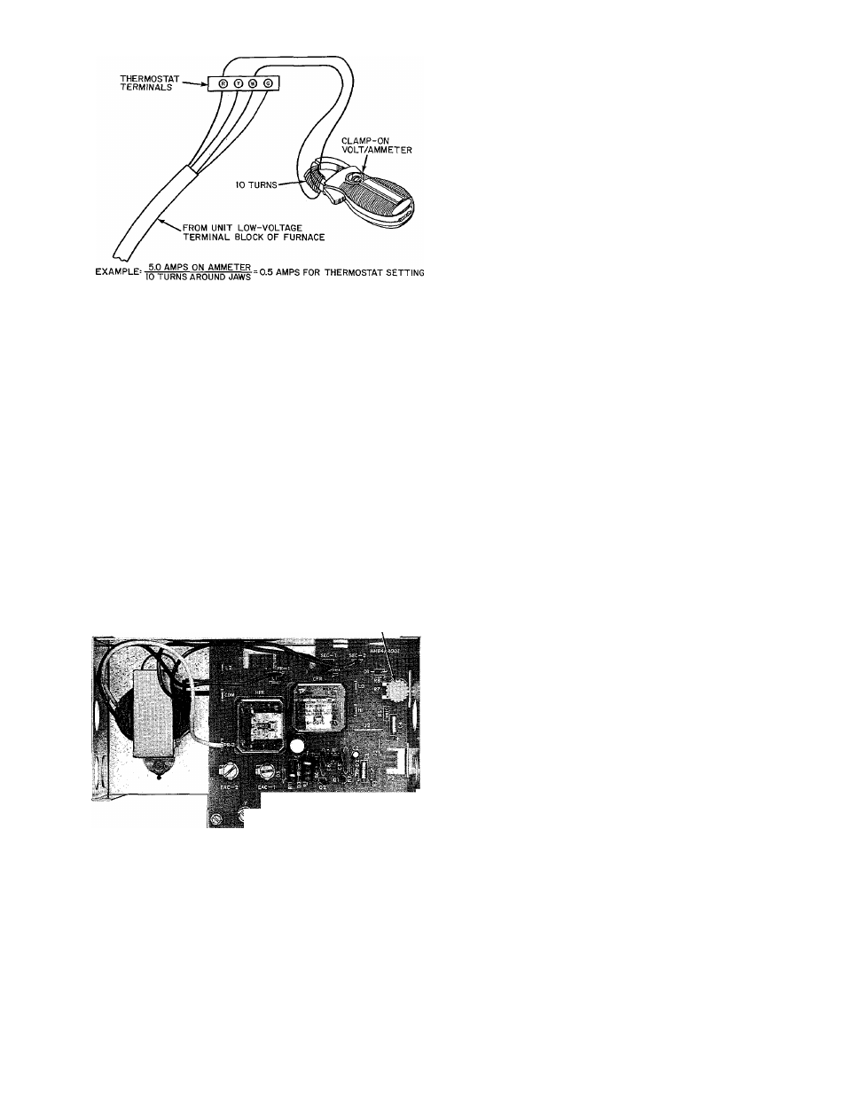
Fig. 14 — Amp Draw Check With Ammeter
BLOWER CONTROL CENTER — Furnace
features a blower control center. This aids installer
and serviceman when installing and servicing unit.
A low-voltage terminal board is marked for easy
connection of field wiring. See Fig. 15.
Main furnace control box features an adjustable
blower-off timing device. Off-timing delay can be
varied over a range of 90 — 240 seconds by turning
off-timing adjustment control in direction indicated
on label attached to side of control box. After a
change in adjustment, time-delay circuit must be
energized at least 4 minutes. This saturates solid-
state circuit so that the off-time delay will be same as
during normal furnace operation. Off-timing adjust
ment is set at factory for delay of approximately
240 seconds. See Fig. 15.
BLOWER OFF-TIME
ADJUSTMENT CONTROL
** ' I? -4' 9 Z
V, ¿J., ^ I*» "4' “s ' c
* »
Fig. 15 — Blower Control Center
2. Wall thermostat calls for heat, closing R and W
circuit. This closed circuit supplies power to
24-volt safety circuit containing limit switch 7 H1,
fusible link lie, manual reset draft safeguard
switch 7H2, and manual reset auxiliary switch
7H3.
3. Simultaneously, PICK coil of gas valve 5F, spark
generator 6F, and inducer-motor relay coil 2D
are energized. Inducer-motor relay contacts 2D
in the 115-volt circuit close, starting inducer
blower motor 3A. Also, another set of contacts
in inducer-motor relay 2D closes in 24-volt
circuit, and locks in inducer-motor relay coil 2D.
Coil is locked in until R and W circuit or safety
circuit opens.
4. When PICK coil of gas valve 5F is energized,
gas flows to pilot. Pilot gas is ignited by a spark
produced by spark generator 6F. Simultaneously,
inducer motor 3A comes up to speed, actuating
flow sensing switch 7V, energizing HOLD coil
of gas valve 5F. PICK coil of gas valve 5F and
spark generator 6F are de-energized when con
tacts of pilot-flame sensing switch 6H move from
normally closed position, breaking circuit to
PICK coil and spark generator. In approximately
50 to 60 seconds normally open pilot-flame
sensing contacts close, making circuit to MGV
(Main Operator) of gas valve 5F. Gas valve 5F
opens in approximately 10 seconds allowing gas
flow to main burners, which are ignited by pilot
6H. Simultaneously, time-delay circuit IIL in
blower control center is energized. Approxi
mately 50 seconds after gas valve 5F opens,
heating relay coil 2E is de-energized, which closes
the 120-volt contacts of heating relay 2E, starting
blower motor 3D on its heating speed.
5. When thermostat is satisfied, circuit between
R and W is broken, de-energizing gas valve 5F,
inducer motor relay 2D, and solid-state time-
delay circuit on printed-circuit board. Gas flow
stops immediately to pilot and main burners.
After approximately 90 — 240 seconds, depend
ing on off-time adjustment setting, heat relay 2E
is energized and blower motor 3D stops.
NOTE; After brief interruption of either electric or
gas supply, furnace will not resume operation until
contacts of pilot-flame sensing switch 6H move from
normally open to normally closed position.
Sequence of Operation
— Refer to wiring
diagram. Fig. 13.
HEATING CYCLE
1. When blower door is in place, 115 volts is sup
plied through blower door interlock switch 9G.
Transformer lA is energized, supplying 24 volts
to heating blower relay coil 2E, which opens
normally closed blower relay contacts 2E in
low-speed circuit of blower motor 3D.
COOLING CYCLE
1. Wall thermostat calls for cooling.
2. The R, G, and Y circuits are energized. Simul
taneously, R and Y circuit starts outdoor con
densing unit, and R and G circuit energizes
cooling relay coil 2F, which closes normally open
contacts 2F, energizing cooling speed winding of
motor 3D and opening normally closed contacts
of cooling relay 2F.