I" =^ori, Page inspection – Carrier 58DH User Manual
Page 2
Attention! The text in this document has been recognized automatically. To view the original document, you can use the "Original mode".
S
-H THERMOSTAT
„„
WIRE ENTRY
13..
-4"
-2l
llll
■H
F"
1
o
.. f__ ’
jr__
Ì
1" 7“
“'2
S POWER
ENTRY
l^DIA KO.
RH.GAS
ENTRY
M
► ---i"
=^ORI
BOLTS (BOTH SIDES)
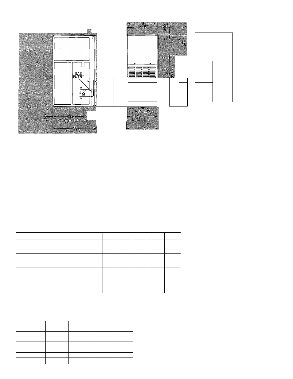
Fig. 3 — Dimensional Drawing (in.)
Installation Procedures
Page
Inspection ........................................................ *
**
Location, Ventilation and Air for
Combustion ..................................................... *
Gas Piping ........................................................... *
Venting ................................................................ *
Supply-Air Plenum Installation
(downflow) ...................................................... 3
Page
Horizontal Attic Installation...................................4
Crawl Space Installation ....................................... 5
Filter Arrangement ............................................... 5
Electrical Connections ......................................... 5
Sequence of Operation ......................................... V
Start-Up and Adjustment ...................................... 8
Care and Maintenance ...........................................8
‘Refer to appropriate sections of ProcSdures for Induced-Draft Gas-Fired Furnaces booklet packed with this furnace.
Table 1 — Clearances (in.)^
FURNACE
TOP
SIDESt
BACK
FRONT
VENT
DOWNFLOW (In Alcove or Closet)|
Single-Wall Vent
1
1
0
6»*
6
Type B1 Double-Wall Vent
1
0
0
3»*
1
HORIZONTAL
(In
Alcove)ft
Single-Wall Vent
1
Iti
0
18
6
Type B1 Double-Wall Vent
0
lit
0
18
1
HORIZONTAL (In Closet)
Single-Wall Vent
2
nt
3
6
6
Type B1 Double-Wall Vent
2
nt
3
3
1
HORIZONTAL (Attic or Unoccupied Spaces)
Type B1 or Type L Double-Wall Vent
1
ut
0
18
1
*Provide a 30-in. service clearance in front of
the furnace.
flndicates supply or return sides \A/hen furnace
is in the horizontal position.
íFor installation on non-combustiblefloorsonly.
For installation on combustible flooring only
when installed on special base (Part No.
58DS900041).
**Alcove
installations
require
18-in.
front
clearance.
ttLine contact permissible only between lines
formed by intersections of the top and 2 sides
of the furnace jacket, and building joists, studs
or framing.
ifClearance shown is for the outlet side. The inlet
side must maintain 6-in. clearance from flue
to combustible materials with single-wall vent.
Table 2 — Dimensions (in.)
Furnace
Size
A
B
C
Vent
Diam
035,040
14-3/16
12-9/16
12-11/16
4
055,060
14-3/16
12-9/16
12-11/16
4
070,080
17-1/2
15-7/8
16
4
090,1 OO(CC)
17-1/2
15-7/8
16i
4
090,1 OO(DC)
21
19-3/8
19-1/2
4
110,120
24-1 /2
22-13/16
23
5
NOI
I
\Mn.i'
l)4().i)SS
,|iul
iibli
size
)m-
n.iccN .ih. iiiM.iILd in d hoii/iMiul poMiion on
conibiixliblc ni,iîi.iial
11 IS
iictcss.ii\ lo
i
.
iisci
I
il
I
LI I IKK I. OIK
in lo ohi.iin icqiiiicd (<-in \Liiipipc
l
I
c
.LI.
1
IK
l
tOI
.1 Mllglc V^dll
Lent
The Carrier induced-draft gas furnace is designed
to accept a Carrier electronic air cleaner and
humidifier.
For accessory installation details, refer to appli
cable installation literature.