Electrical connections – Carrier 58DH User Manual
Page 5
Attention! The text in this document has been recognized automatically. To view the original document, you can use the "Original mode".
Crawl Space Installation
— The Model 58DH
furnace can be installed horizontally with either
the left-hand or right-hand side up. In crawl space,
furnace can either be hung from floor joist or in
stalled on suitable blocks or pad. Furnace can be
suspended from each corner by hanger bolts (use
four 3/8-in. all-thread rods cut to desired length,
1 X 3/8-in. flat washer, 3/8-in. lock washer, and
3/8-in. nut). Dimples are provided for hole loca
tions. See Fig. 3.
Crawl space installation is very similar to attic
installation. Refer to Horizontal Attic Installation,
Install Furnace (Steps 1,2,3). Installation of sheet
metal shield in front of louvered control panel is
covered in Step 4. For crawl space installation, the
same size sheet metal shield must be installed above
louvered control panel. When installing furnace in
horizontal position in a crawl space, extend sheet
metal shield over furnace top sufficiently to cover
gas pipe entry hole.
Filter
Arrangement
—
Two
factory-supplied
filters are shipped in blower compartment. After
return air duct has been connected to furnace, install
filters in a V-formation inside return air plenum.
See Fig. 10 and Table 5 for horizontal applications.
See Fig. 11 for downflow applications.
Accessory filter retainer and duct flange kits are
available. See Fig. 9 and 10 for typical installations.
WARNING: \c\cr operate unit \\ithout a lilter.
or with filter acccs:» door rcmo\ed.
Table 5 — Filter Retainer (in.)
Furnace Size
Dim. A (Fig. 10)
035—060
15-3/16
070—lOO(CC)
14-1/2
090—lOO(DC)
13-9/16
110—120
12-1/4
Fig. 11 — Downflow Filter Arrangement
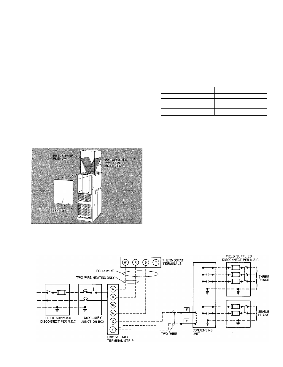
Electrical Connections
LINE-VOLTAGE WIRING
I M F O K I
\ \ l .
UeliiK
pioteed
ng
eL^-
trical connections, make certain that \oltagc,
lrequenc\. and phase correspond lo that speci
fied on unit rating plate. Also, check to be sure
that set\ice pro\ided by utility is sufficient to
handle additional load imposed by this equip
ment. Reler to tinit rating plate for equipment
electrical requirements.
( \l I ION Do not (.oiineei .iliiminiini w i i e
Iviweeii diNeomiLi.l '■wneh .oii! iMin.ue Make
all electrical connections in accordance with
N . i t i o n . i l I l e e t i i c . i l I ode. WSl \l l'.\
70-1984. and any local codes or ordinances that
Fig. 12
Heating and Cooling Application Wiring Diagram
5