Electrical controls and wiring – Carrier 58DH User Manual
Page 10
Attention! The text in this document has been recognized automatically. To view the original document, you can use the "Original mode".
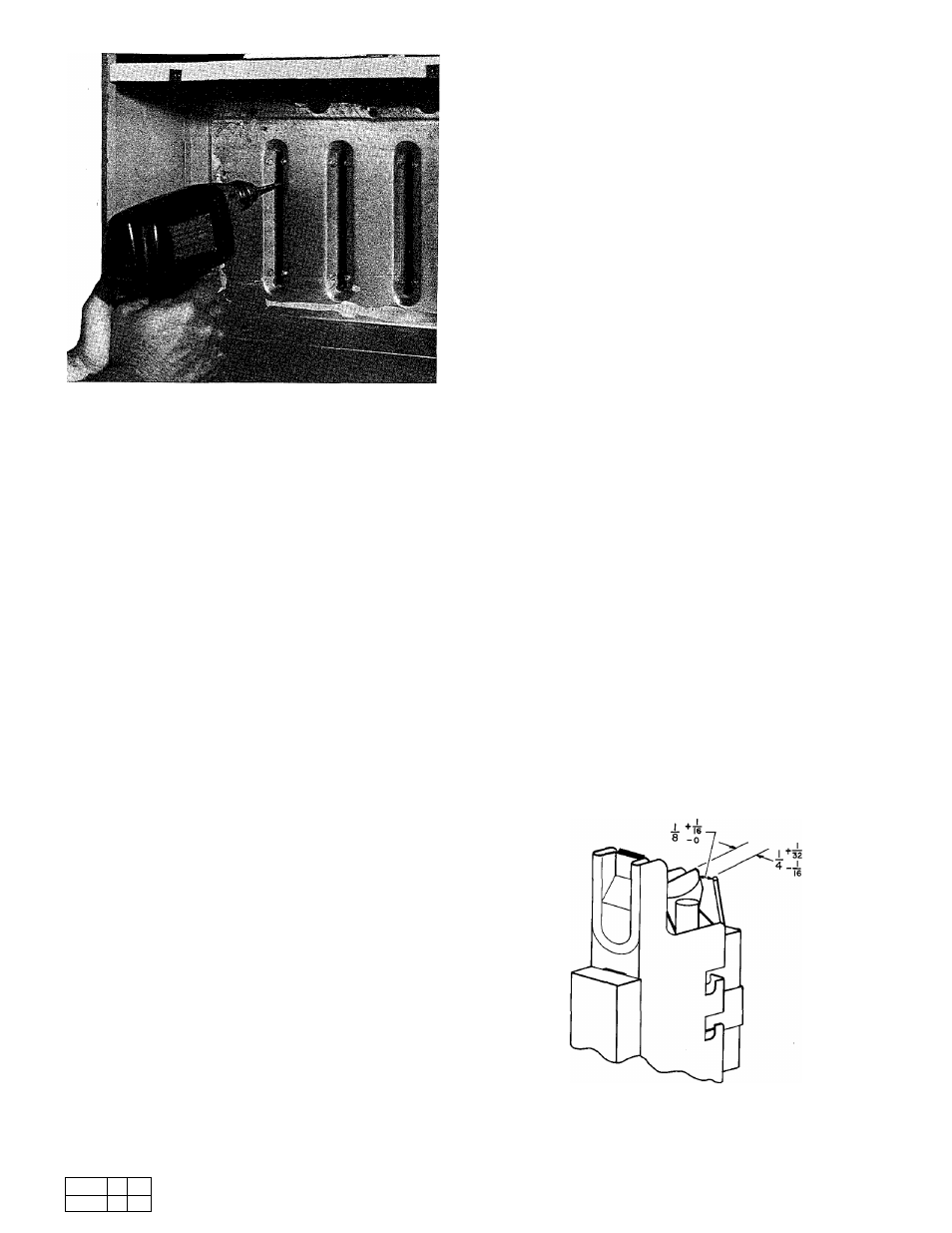
Fig. 18 — Cleaning Heat Exchanger Cell
2) Insert brush end of cable into upper
opening of cell and slowly rotate with
drill. Do not force cable. Gradually insert
at least 3 ft of cable into 2 upper passes
of cell. See Fig; 18.
3) Work cable in and out of cell 3 or 4 times
to sufficiently clean. Do not pull cable
with great force. Reverse drill and grad
ually work cable out.
4)
Remove burner assembly and flame
radiators. Identify gas valve leads.
5) Insert brush end of cable in lower open
ing of cell. Clean 2 lower passes of cell in
same manner as 2 upper passes.
6) Repeat above procedures until each cell
in furnace has been cleaned.
7) Using vacuum cleaner, remove residue
from each cell.
8) Using vacuum cleaner with soft brush
attachment, clean burner assembly.
9) Reinstall burner assembly and flame
radiators. Take care to center flame
radiators in the cell openings. Refer to
furnace wiring diagram when reconnect
ing gas valve leads.
11. After cleaning flue openings, check sealant on
flue collector to ensure it has not been damaged.
If new sealant is needed, contact dealer.
12. Replace flue choke.
13. Clean and replace flue collector assembly,
making sure all 8 screws are secure.
14. Replace 4 screws that secure relief box to blower
shelf.
15. Reconnect 2 wires to safeguard switch.
16. Reconnect wire harness edge connector to side
of inducer control box.
17. Reconnect vent pipe to relief box. Reinstall
pipe enclosure.
18. Replace blower door only.
19. Turn on power and gas.
20. Set thermostat. Check furnace for proper
operation.
21. Check for gas leaks.
22. Replace control door.
\\ \ R M N t i
111;, a iiKiuh oi m l u i opui
iLimc to thi-Lk loi li.iN Ir.ikN I
< 1
MMp cirui
Pilot
— Check pilot and clean if necessary at be
ginning of each heating season. Pilot flame should
be high enough for proper impingement of safety
element and to light burners. Remove accumulation
of soot and carbon from safety element or sensing
probe and check electrode position. See Fig. 19.
Flame Radiators (if used)
— Radiators should be
checked for distortion and deterioration at the be
ginning of each heating season. Replace if necessary.
Electrical Controls and Wiring
NOTE: There may be more than one electrical
supply to unit.
With power to unit disconnected, check all elec
trical connections for tightness. Tighten all screws
on electrical connections. If any smoky or burned
connections are noticed, disassemble connection,
clean all parts and stripped wire, reassemble prop
erly and securely. Electrical controls are difficult
to check without proper instrumentation; therefore,
reconnect electrical power to unit and observe unit
through one complete operating cycle. If there are
any discrepancies in operating cycle, contact dealer
and request service.
Fig. 19 — Position of Electrode to Pilot (in.)
For replacement items use Carrier Specified Parts.
Manufacturer reserves the right to discontinue, or change at any time, specifications or designs without notice and without incurring obligations.
Book
1
4
Tab
6
a
8
a
Form58DH-3SI Supersedes 58DH-2SI
Printed in U.S.A.
12-84
PC 101
Catalog No. 535-814