Legend, Fig. 13 — line to line wiring diagram – Carrier 58DH User Manual
Page 6
Attention! The text in this document has been recognized automatically. To view the original document, you can use the "Original mode".
See Fig. 12 for wiring diagram showing proper
field high- and low-voltage wiring. Use separate
fused branch electrical circuit containing proper
fuse or HACR (Heating, Air Conditioning and
Refrigeration)-type circuit breaker for this furnace.
A disconnecting means must be located within sight
from, and easily accessible from, the furnace.
Blower door switch may be acceptable in some areas
as a disconnect.
\\ \ K \ l \ ( i ; l i i i i i a c c tniisl be decli ic.ill\
giouiuled in .icimdaiicc w i l l i h'calciuli-s.md tlic
N.ilioticd I l i c i i i c t oili-. WM \l l’\ '() F).s4
Du nui use gas piping .i' an elecliieal giuinid
If line voltage wiring to unit is encased in non-
metallic sheath, connect incoming ground wire to
grounding wire inside furnace junction box. If
metallic conduit is used, it will serve as ground.
LOW-VOLTAGE WIRING — Make field low-
voltage connections at low-voltage terminal strip.
See Fig. 12.
NOTE: Use American Wire Gage (AWG) No. 18
color-coded copper thermostat wire for lengths up
to lOOfeet. Above 100 ft, use AWG No. 16 wire.
I N I T O R I N \ l I It. ihi.imusi.li
.ni;i-
upaiui musi he sii lu nurch .imp i l i . i w u l
i m s
v a l w and ek-iiiical cumpuiienls m R-\\ i i K i i i i
.Accurate amp draw readings can be obtained at
thermostat subbase terminals R and W. l igure
14 illustrates an easy method of obtaining actual
.imp d i . i u l a k e iimp le.uliii'.' a l l e i bluwei
motor has started.
Room thermostat should be located where it will
be in natural circulation path of room air. Avoid
locations where thermostat would be exposed to
cold-air infiltration, drafts from windows, doors,
or other openings leading to outside, or exposed
to air currents from warm- or cold-air registers; or
to exposure where natural circulation of air is cut
off—such as behind doors, above or below mantels,
shelves, etc.
Thermostat should not be exposed to heat from
nearby fireplaces, radios, televisions, lamps, or rays
from sun. Do not mount thermostat on a wall con
taining pipes, warm-air ducts, or a flue or vent that
could affect its operation. Any hole in the plaster or
panel through which thermostat wires pass should
be adequately sealed with suitable material to pre
vent drafts from affecting thermostat.
1A
2D
2E
2F
ЗА
3D
4A
5F
6C2
6
F
6
H
7H1
7H2
7H3
7V
9G
lOBt
10B2
10B3
10B4
10B5
10B6
lie
11E -
11L -
TP1
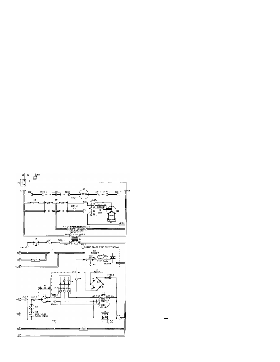
LEGEND
-Transformer 115-VAC/24-VAC
-Inducer Motor Relay DPST-N.O.
- Heating Blower Relay(HFR) DPST-N.C.
- Cooling Blower Relay (CFR) DPDT
- Inducer Motor
- Blower Motor
- Run Capacitor
- Gas Valve (Redundant)
- P.C. Board (Inducer Control)
- Spark Generator (Solid-State)
- Pilot-Flame Sensing Switch SPOT (733B)
-Limit Switch SPST-N.C.
-
Draft-Safeguard
Switch
(SPST-N.C.)
Manual-Reset
-Auxiliary Limit Switch (SPST-N.C.) Manual-Reset
(When Used)
- Flow Sensing Switch SPOT
- Blower Door Interlock Switch SPST-N.O.
- Edge Connector (Furnace Control Board)
- Edge Connector (Inducer Control Board-7 CKT)
- Edge Connector (Inducer Control Board-2 CKT)
- Pilot Connector
- Factory Test Points
- Blower Motor Connector
- Fusible Link (Overtemperature)
- Equipment Ground
■ Adjustable Resistor (Off Time)
- Test Point
Factory Wiring (115 VAC)
_____ Factory Wiring (24 VAC)
_____Field Wiring (115 VAC)
-
. Conductors on 6C1 (Furnace Control Board)
f/// Conductors on 6C2 (Inducer
Control Board)
Screw Terminal for Field Wiring
1
1/4-in. Quick-Connect Terminals
Fig. 13 — Line to Line Wiring Diagram