Fig. 4 — floor opening for concrete slab, Installation – Carrier 58DH User Manual
Page 3
Attention! The text in this document has been recognized automatically. To view the original document, you can use the "Original mode".
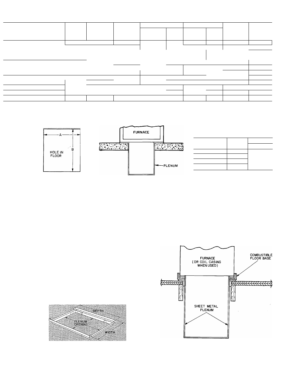
Table 3 — Ratings and Performance*
FURNACE
SIZE
TEMP
RISE
RANGE (F)
HEATING
COOLING
APPROX
SHIP.
WT (lb)
INPUT
(Btuh)
CAPACITY
(Btuht)
Ext
Static
Pressure
(in. wg)
Cfm
Ext
Static
Pressure
(in. wg)
Cfm
MOTOR
HP & TYPE
OJS 100CC
43,000
3b,000
20- 50
0 12
1060
0 50
1 171
1 '3PSC
132
040-100CC
48,000
38,000
25-55
.12
1060
0.50
1 1 / 1
1 /3 PSC
132
055-1OOCC
;
6.1,UCiO
beo-'iooc'c i /1000
52,000
•10 7(J
012
1080
0.50
1157
1 3PSC
142
57,000 \ 45-75
0 12
1080
0.50
1157
1 3PSC
142
070-1 OOCC f 86,OCiO
71 000
40-70
015
1240
0 50 ' 1553
1 2 PSC
163
080-1 OOCC
95,000
77,000
45-75
0.15
1240
0.50
1553
1/2PSC
16.1
OiJO loncr
107,000
88,000 ¡ 55-85
0 20 ! 1348
0 50
1590
1 2 PSC
178
1 100 1 OOCC
119,000
98,000
60-90
_!20 I 1348
0.50
1590
1 2 PSC
178
OOlllOODC
107,000
88,000
50 80
0.20
13i)0
0 50
1929 ! 1 2PSC
188
100-100DC
119,000
■ ■ )bo"'
97,000
3-85
0 2n
1350
0.50
1929
1/2PSC
188
^ iio-ii)ocf;
106,000
40 '7Ó
0 20
193/
0 50
2010
1 2PsSC
208
120-1 OOCC
143,000
117,000
50-80
0.20"
1937
0.50
2010
1/2PSC
208
. ' I r. Models meet or exceed California low NOx requirements.
PSC — Permanent Split Capacitor
*Ratings are certified for altitudes to 2000feet. For elevations above 2000ft, reduce ratings 4% for each 1000ft above sea level.
tOetermined by U.S. Government Standard test procedures using outdoor combustion air method.
Table 4 — Opening Dimensions
(in.)
Furnace
A
B
Size
Heat-Only
035—060
13-1/8
070—lOO(CC)
16-7/16
19-5/8
090—100(00
19-7/8
110—120
23-7/16
Fig. 4 — Floor Opening
for Concrete Slab
Fig. 5 — Furnace on a Concrete
Slab
INSTALLATION
Supply-Air Plenum (Downflow)
INSTALLATION ON CONCRETE SLAB
1. See Fig. 3 for dimensions and location of supply-
air opening in furnace bottom.
2. Construct hole in floor. See Fig. 4 and Table 4.
3. Place plenum and furnace. See Fig. 5.
INSTALLATION ON COMBUSTIBLE FLOOR
1. Read installation instructions packaged with
accessory combustible floor base.
2. Cut and frame hole in floor. See Table 1 of in
stallation instructions packaged with combus
tible floor base. If this requires cutting a floor
joist, tie ends of cut joist into adjacent joists for
proper floor support.
3. Assemble and install combustible floor base per
instructions packaged with base.
4. When completed, install combustible floor base,
plenum, and furnace (or coil casing when used).
See Fig. 7.
Fig. 6 — Accessory Combustible Floor Base
Fig. 7 — Furnace, Plenum, and
Base Installed on Combustible Floor