Lu > % o, O■d o, 15 cn Page 9: 3 05 o)
Attention! The text in this document has been recognized automatically. To view the original document, you can use the "Original mode".
320
300
280
260
240
in
a.
lU
>
%
o
>
□:
UJ
to
o
■D
O
_l
^ 220
15
cn
UJ
tc
Q.
200
180
160
COOLING CYCLE
m
CFM-860
:WET BULB TEMP AIR
ENT INDOOR UNIT
:75F
62
f
:
67 F
85 F^
172 F
I I 5 F
105 F
95 F:
DRY BULB TEMP AIR
ENT OUTDOOR UNIT
66 68 70 72 74 76 78 80 82 84 86 88
PRESSURE AT SUCTION SERVICE VALVE (PSIG)
Fig. 9 — 38QF024 with 40AQ024,030.
28HQ,VQ024 or 030, 40FS075 with
28HQ,VQ042 Cooling Cycle Charging Chart
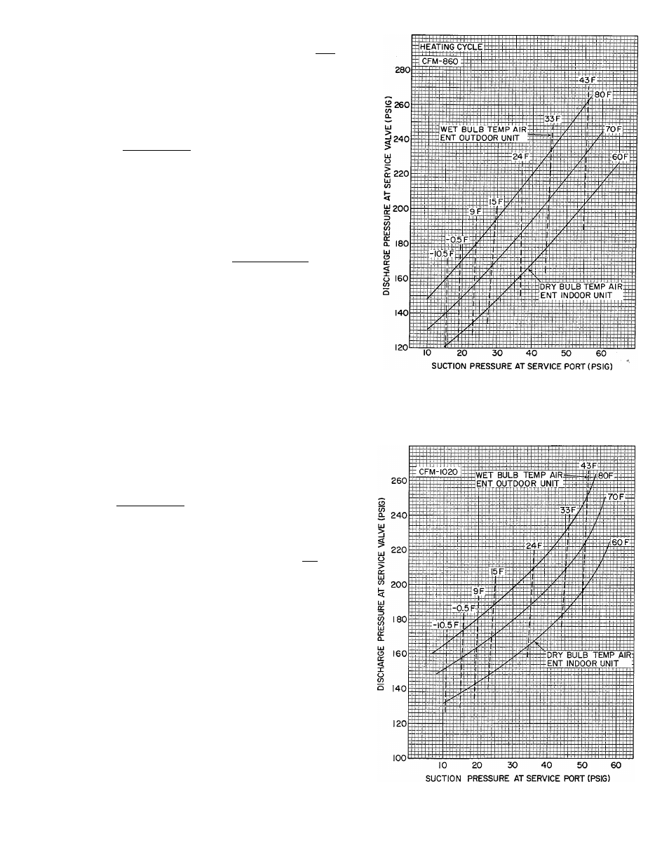
Fig. 10 — 38QF024 with 40AQ024,030,
28HQ,VQ024 or 030, 40FS075 with 28HQ,
VQ042 Heating Cycle Operation Check Chart
340
5 320
if)
Q.
UJ
300
%
UJ
O
^ 280
ui
V)
9
o 260
q
:
3
05
O)
UJ
01
a.
240
220
200
180
CFM-1020
WET BULB TEMP AIR
ENT INDOOR UNIT
62 F
75 F
:67F:
95 F
72 F:
II5F±
I05F
DRY BULB TEMP AIR:
ENT OUTDOOR UNIT
85 F
66
70
74
78
82
86
90
PRESSURE AT SUCTION SERVICE VALVE(PSIG)
Fig. 11 — 38QF030 with 28AR036,
28HQ,VQ036 or 40AQ036, 40DQ030
Cooling Cycle Charging Chart
Fig. 12 — 38QF030 with 28AR036,
28HQ,VQ036 or 40AQ036, 40DQ030
Heating Cycle Operation Check Chart