Step 2 — mount outdoor heat pump – Carrier 38QF User Manual
Page 2
Attention! The text in this document has been recognized automatically. To view the original document, you can use the "Original mode".
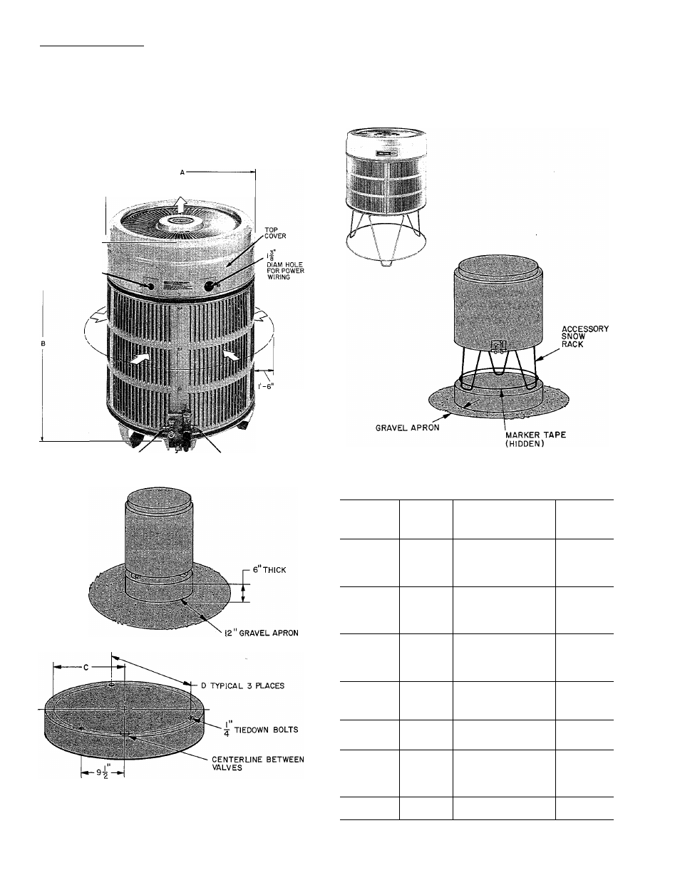
Top Cover Removal — Top cover can be removed
for wiring or servicing heat pump. Loosen decora
tive strip and slide down off screw heads. Remove
3 screws in connector plate and 2 screws on front of
unit. Loosen remaining 4 screws. Lift top from unit
(see Fig. 1).
Step 2 — Mount Outdoor Heat Pump
ON THE GROUND: MOUNT UNIT ON A
SOLID, LEVEL CONCRETE PAD (see Fig. I).
4-0"0VERHEAD SPACE REQUIRED
FOR SERVICE AND AIRFLOW
7"
8
DIAM HOLE
FOR CONTROL
WIRING
AIRFLOW AND
SERVICE
CLEARANCE
LIQUID VALVE SERVICE PORT
/
VAPOR VALVE SERVICE PORT
AIRFLOW
SUCTION SERVICE PORT
CONCRETE MOUNTING PAD
Fig. 1 — Dimensions, Connections and
Mounting Pad (Refer to Table 2)
Swing 3 legs down and lock in position, except when
using accessory rack. Use accessory heat pump rack
(Fig. 2) in areas where prolonged subfreezing tem
peratures or heavy snow occur. (Refer to installation
instructions included with rack.) Drainage holes in
unit base must not be obstructed.
Fig. 2 — Accessory Mounting Rack
Table 1 — Carrier Approved 38QF Systems
OUTDOOR
UNIT
38QF
REQUIRED
OUTDOOR
PISTON
SIZE
INDOOR
UNIT
MODEL &
SIZE
REQUIRED
INDOOR
PISTON
SIZE
40AQ018
52
28HQ/VQ018
52
018
42
40AQ024
55*
28HQ/VQ024
55*
40FS075,28HQ/VQ042
61
40AQ024
59
28HQ/VQ024
59
024
46
40AQ030
61*
28HQ/VQ030
61*
40FS075,28HQ/VQ042
65
40AQ030
67
28HQ/VQ030
67
030
59
40DQ030
67
40AQ036
70*
28HQ/VQ036
70*
40AQ036
70
036
61
28HQ/VQ036
70
40QB/QH042
73*
28HQ/VQ042
73*
40QB/QH042
76
042
63
28HQ/VQ048
78
40QB/QH048
78
40QB/QH048
84
28HQ/VQ048
84
048
76
40QB/QH060
86*
40QB/QH062
86*
28HQ/VQ060
86*
060
82
40QB/QH060
40QB/QH062
96
^Factory-supplied piston packages shipped in outdoor unit. Replace remain
ing indoor pistons with size indicated.