Fig. 7 — high- and low-voltage connections, Start-up – Carrier 48GH User Manual
Page 8
Attention! The text in this document has been recognized automatically. To view the original document, you can use the "Original mode".
SINGLE-STAGE HEAT & COOL-MANUAL CHANGEOVER
(p ®
I FIELD
I SPLICE
CONTACTOR TERMINALS (SEE
UNIT WIRING LABEL)
b ^ ^
V]
I]
-J
3
O
>•
GÛ
a:
LOW-VOLTAGE
PIGTAIL LEADS
.POWER
I SUPPLY
CONTROL BOX I
/ | FIELD-SUPPLIED
HIGH-VOLTAGE PIGTAIL LEAD / „"gCONNECT
HIT I
FIELD-SUPPLIED CONDUIT
3-PHASE UNITS ONLY
-------FIELD LOW-VOLTAGE WIRING ■
-------FIELD HIGH-VOLTAGE WIRING ■
-FACTORY LOW-VOLTAGE WIRING
-FACTORY HIGH-VOLTAGE WIRING
NOTE;
For manual changeover applications, use thermostat part no
HH01AD042 with subbase part no HH93AZ042; or thermostat
part no. HH01AD040 with subbase part no HH93AZ040
For automatic changeover, use thermostat part no HH07AT074
with subbase part no HH93AZ096; or thermostat part no
HH10AD041 with subbase part no HH93AZ041
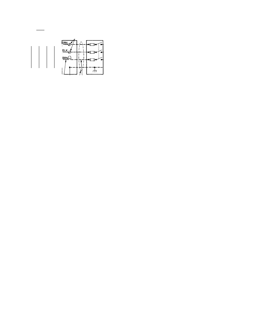
Fig. 7 — High- and Low-Voltage Connections
When operating Models 48GL018 thru042 single
phase units or Models 48GH036 thru 048 three-
phase units at 208 volts, disconnect orange
transformer-primary lead from contactor. See unit
wiring label and Fig. 7. Remove tape and cover
from terminal on the end of red transformer
primary lead. Save cover. Connect red lead to
contactor terminal from which orange lead was
disconnected.
Using cover removed from red lead, insulate
loose terminal on orange lead. Wrap cover with elec
trical tape so that metal terminal cannot be seen.
NOTE: For some units, the factory-wired blower-
motor speed connections may require changing for
208-volt operation to ensure adequate airflow at the
rated external static pressure. See unit wiring label.
Insulate all unused motor leads following same
procedures described for transformer leads.
LOW-VOLTAGE CONNECTIONS — Use a suit
able room thermostat as specified on unit wiring
label.
Locate room thermostat on an inside wall in space
to be conditioned where it will not be subjected to
either a cooling or heating source, or direct exposure
to sunlight. Mount thermostat 4 to 5 ft above floor.
Use No. 18 AWG color-coded, insulated (35 C
minimum) wires to make low-voltage connections
between thermostat and unit. If thermostat is
located more than 100 ft from unit (as measured
along the low-voltage wires), use No. 16 AWG
color-coded, insulated (35 C minimum) wires.
A grommeted, low-voltage inlet hole is located
in a panel adjacent to control access panel. See
Fig. 1. Run low-voltage leads from thermostat, thru
inlet hole, and to low-voltage flagged pigtail leads
that run thru a hole in bottom of unit control box.
See Fig. 6. Connect thermostat leads to the pigtail
leads as shown in Fig. 7.
HEAT ANTICIPATOR SETTING — Room ther
mostat heat anticipator must be properly adjusted
to ensure proper heating performance. Set heat
anticipator to approximately 0.85 amps. Use an
ammeter to determine exact required setting.
Failure to make a proper heat anticipator adjust
ment will result in improper operation, discomfort
to occupants of conditioned space, and inefficient
energy utilization; however, required setting may be
changed slightly to provide a greater degree of
comfort for a particular installation.
START-UP
Unit Preparation
WARNiNG/DANGER: Failure to observe ifee
foliowirig warnbigs could result m serious
personal injury;
1. Follow recognized safety practices and wear
protective goggles when checking or servicing
refrigerant system.
2. Do not operate compressor or provide any
electric power to unit unless compressor
terminal cover is in place and secured.
3. Do not remove compressor terminal cover until
all electrical sources have been disconnected.
4. Relieve all pressure from system before touching
or disturbing anything inside terminal box if a
refrigerant leak is suspected around compressor
terminals.
5. Do not use a torch to remove any component.
System contains oil and refrigerant under
pressure. To remove a component, wear protec
tive goggles and proceed as follows:
a. Shut off gas supply and then electrical
power to unit.
b. Relieve all pressure from system.
c. Cut component connecting tubing with
tubing cutter and remove component from
unit.
d. Carefully unsweat remaining tubing stubs
when necessary. Oil can ignite when exposed
to torch flame.
PRE-START-UP PROCEDURES ^ Proceed as
follows to inspect and prepare unit for initial
start-up:
1. Remove all access panels.
2. Read and follow instructions on all WARNING,
CAUTION, and INFORMATION labels
attached to or shipped with the unit, such as
blower rotation labels, etc.