Carrier 48GH User Manual
Page 11
Attention! The text in this document has been recognized automatically. To view the original document, you can use the "Original mode".
#
Proceed as follows to measure and change
manifold pressure:
a. Turn off gas to unit.
b. Remove pipe plug on gas valve outlet identified
as PRESS TAP, then connect manometer at
this point.
c. Turn on gas to unit and start heating section.
d. Measure and change manifold pressure with all
burners fired to obtain desired gas input.
e. Turn off gas to unit, remove manometer from
gas valve, and replace pipe plug.
ADJUSTING BURNER AIR SHUTTERS —
After burners have operated at full input for at least
10 minutes, adjust primary air to each burner to
ensure optimum heating performance. Make these
adjustments when unit is being installed and during
routine maintenance inspections at beginning of
each heating season. Be sure that each burner is
clean and free of deposits before adjusting primary
air.
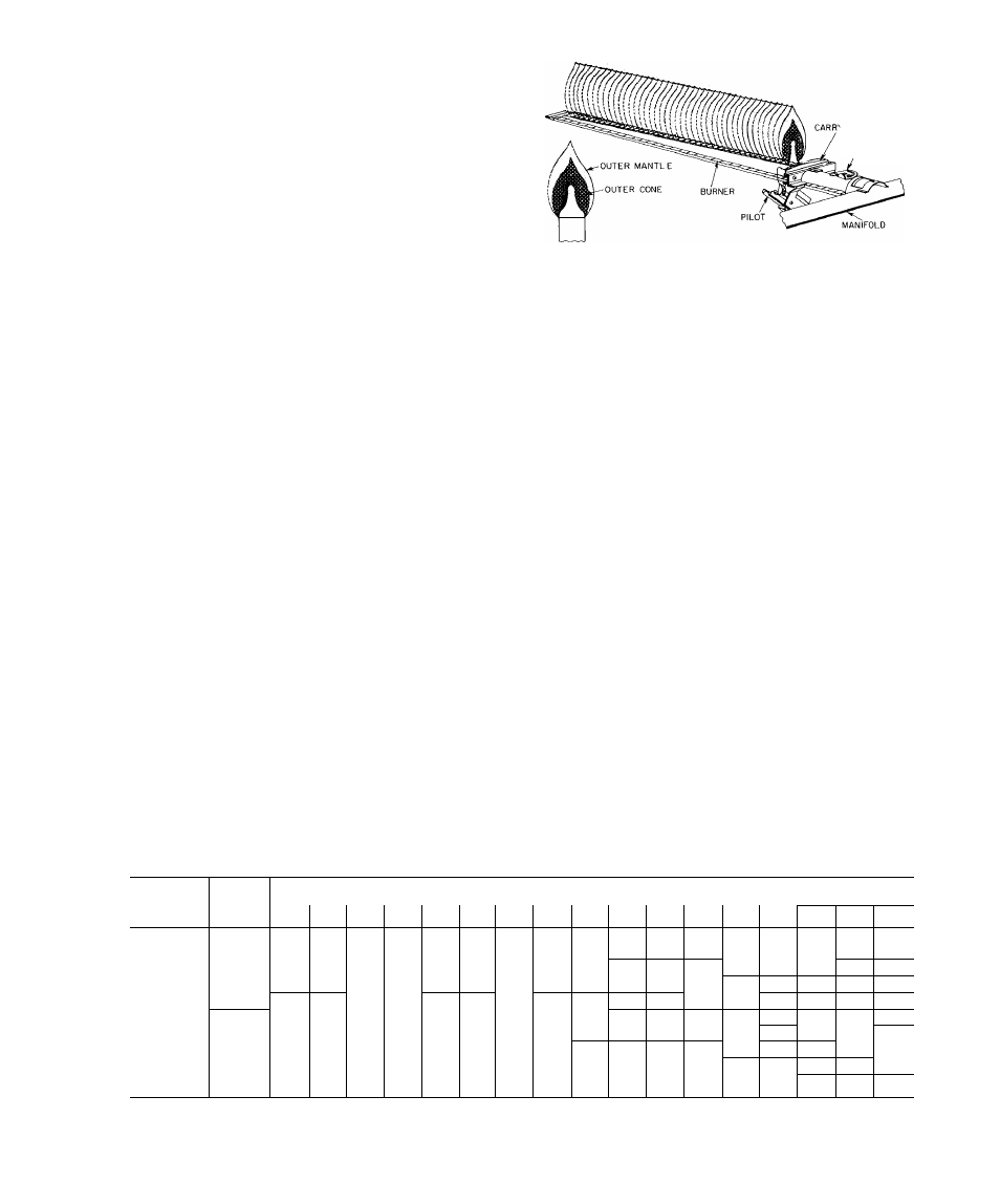
The primary air to each burner is regulated by
burner air shutter on each burner. See Eig. 8 for
location of burner air shutter. With all burners
operating, adjust primary air to each burner as
follows:
1. Eoosen locking screw that secures air shutter
in place on burner, then partially close air shutter
until a slight yellow tip appears on top of burner
flames.
2. Open air shutter very slowly until yellow tip just
disappears, then secure air shutter in place with
locking screw.
3. Repeat steps 1 and 2 for each burner.
After air shutter adjustments have been com
pleted, observe that flames on each burner are light
blue and “soft” in appearance, and that flames are
same height along the entire length of each burner.
See Fig. 8.
AIR
SHUTTER
Fig. 8 — Burner Flames
BLOWER HEAT-RELAY OPERATION —
Heating relay (see Fig. 6 and unit wiring diagram) is
located in control box and adjusts to permit either
longer or shorter OFF cycles. The ON cycle auto
matically adjusts as OFF cycle changes. Adjusting
lever on relay is factory-set at center position to
provide optimum performance for most installa
tions. On unusual installations, or where line voltage
is considerably above or below rated voltage, length
of time blower remains on may require increasing or
decreasing. To increase blower operation time,
move adjusting lever toward right-hand position.
In this position, control makes contact sooner and
takes maximum time to break contact. To decrease
blower operation time, move lever toward left-
hand position.
AIRFLOW AND TEMPERATURE RISE —
Temperature rise is temperature difference between
air in return duct and air in discharge duct at unit.
Heating section of each size of unit is designed and
approved for heating operation within temperature
rise range stamped on unit rating plate.
Table 4 shows the approved temperature rise
range for each unit and air delivery (cfm) at various
temperature rises for both AGA-certified gas
input ratings. Heating operation airflow must
produce a temperature rise that falls within
approved range.
Table 4 — Air Delivery (Cfm) at Indicated Temperature
Rise and Rated Heating Input
MODEL
48
HEATING
INPUT
(Btuh)
TEMPERATURE RISE (F)
35
37 5
40
42 5
45
47,5
50
52 5
55
57 5
60
62 5
65
67 5
70
72 5
75
GL018,024,
40,000*
794
741
694
654
617
585
556
529
505
483
463
444
427
412
397
383
370
030
50,000
1032
963
903
850
802
760
722
688
657
628
602
578
556
535
516
498
481
GH024.030
60,000* 1190 1111 1042
980
926
877
833
794
758
725
694
667
641
617
595
575
556
GL036.O42
75,000
1548 1444 1354 1275 1204 1140 1083
1032
985
942
903
867
833
802
774
747
722
GH042
80,000*
1587 1481 1389 1307 1235 1170 nil
1058 1010
966
926
889
855
823
794
766
741
GL048
100,000
2063 1926 1806 1699 1605 1520 1444
1376 1313 1256 1204 1156 1111 1070 1032
996
963
GH036.048
100,000* 1984 1852 1736 1634 1543 1462 1389
1323 1263 1208 1157 1111 1068 1029
992
958
926
GL06O
1 25,000
2579 2407 2257 2124 2006 1901 1806
1720 1641 1570 1505 1444 1389 1337 1290 1245 1204
GH060
120,000* 2381 2222 2083 1961 1852 1754 1667
1587 1515 1449 1389 1333 1282 1235 1190 1149 1111
150,000
3095 2889 2708 2549 2407 2281 2167
2063 1970 1884 1806 1733 1667 1605 1548 1494 1444
“These inputs are the minimum rated inputs using factory-installed burner
orifices Higher inputs shown for each size are the maximum rated inputs
using field-installed, optional burner orifices that are indicated on unit
rating plate
NOTE: Models 48GL018,024,036; 48GH024,030 have an approved tem
perature rise range of 35 to 75 F All other units have an approved tempera
ture rise range of 45 to 75 F
11