Service – Carrier 48GH User Manual
Page 17
Attention! The text in this document has been recognized automatically. To view the original document, you can use the "Original mode".
FIELD
POWER
SUPPLY
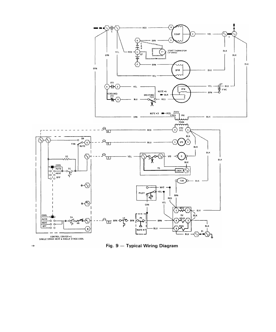
SCHEMATIC DIAGRAM
The set of normally open contacts of energized
indoor fan relay (cooling) closes and completes
circuit thru indoor fan motor. The blower motor
starts instantly.
The cooling cycle remains on until room tempera
ture drops to a point that is slightly below cooling
control setting of room thermostat. At this point,
thermostat cooling bulb tilts and breaks circuit
between thermostat terminal R to terminal Y and G.
These open circuits de-energize contactor and indoor
fan relay (cooling) and Time Guard II circuit. The
condenser, compressor and blower motors stop. The
unit is in a standby condition, waiting for next call
for cooling from room thermostat. Time Guard II
circuit prevents short-cycling of compressor by a
5-minute time delay between stop and restart.
SERVICE
To ensure continuing high performance, and to
minimize the possibility of premature equipment
failure, periodic maintenance must be performed on
this equipment. This combination heating/cooling
unit should be inspected at least once each year by a
qualified service person.
17