Caution; doling opersaion, recota, Wt , raimg plate, Teas – Carrier 48GH User Manual
Page 13: Bivtk, Cotmìctìo-m
Attention! The text in this document has been recognized automatically. To view the original document, you can use the "Original mode".
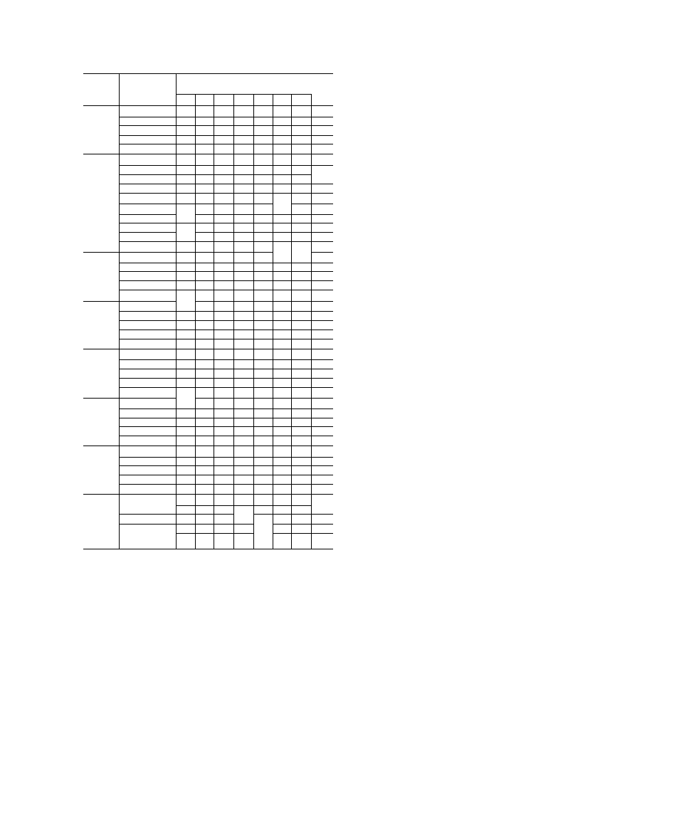
Table 5 — Refrigerant (R-22) Charge
Check Charts*
MODEL
48
EVAPORATOR
AIR INLET
CONDENSER AIR INLET TEMP (F)
WET BULB (F)
65
70
75
80
85
90
95
100
55
138 156 174 192 211 229 247 265
60
143 161 178 196 213 231 249 266
GL018
65
148 165 182 199 216 233 251 268
70
153 169 186 202 219 236 252 269
75
158 174 190 206 222 238 254 270
55
157 170 183 197 210 223 238 253
60
158 172 185 198 212 225 240 255
GL024
65
160 173 187 200 214 228 243 259
70
161 175 189 202 217 232 247 262
75
163 177 191 205 220 235 251 267
55
148 163 178 193 208 224 239 254
60
150 165 181 195 211 226 241 256
GH024
65
151 167 182 197 213 228 243 258
70
153 169 184 199 215 230 245 261
75
155 171 186 202 217 232 247 263
55
163 178 193 208 220 235 247 262
GL030,
GH030
60
165 180 195 210 223 238 251 266
65
167 182 197 212 226 241 255 270
70
169 184 199 214 229 244 259 274
75
171 186 201 216 232 247 263 276
55
172 186 200 214 229 244 260 274
60
175 190 204 218 233 248 264 278
GL036
65
178 193 208 222 238 252 268 282
70
182 197 212 226 241 256 271 286
75
185 200 215 230 245 260 275 290
55
168 182 196 209 223 238 253 268
60
171 185 199 213 228 243 259 276
GH036
65
173 188 203 217 233 248 266 283
70
175 191 206 221 237 253 271 288
75
176 193 209 225 242 258 275 292
55
177 192 208 224 239 253 269 285
GL042,
GH042
60
180 195 211 227 243 258 274 290
65
183 198 214 230 247 263 279 295
70
186 201 217 233 251 268 284 300
75
189 204 220 236 255 273 289 305
55
171 182 193 204 216 228 242 257
GL048.
GH048
60
176 188 200 211 224 237 251 265
65
181 193 206 218 232 245 258 274
70
185 197 210 223 238 252 267 282
75
188 201 215 228 243 258 274 291
55
173 190 204 219 236 251 266 280
GL060.
GH060
60
175 192 207 223 240 256 272 287
65
177 194 210 227 244 261 278 294
70
179 196 213 231 248 266 284 301
75
181 198 216 235 252 271 290 308
*Table shows recommended discharge pressures at compressor (psig)
5. Evaluate system performance and refrigerant
charge by comparing recorded readings with
operating pressure/temperature tag.
6. Make slight adjustment to refrigerant charge
when necessary.
NOTE: If problem causing inaccurate readings is
a refrigerant leak, see Unit Preparation — RE
FRIGERANT LEAKS.
INDOOR AIRFLOW AND AIRFLOW AD
JUSTMENTS — Models 48GH/GL have direct-
drive blower motors. All motors are factory
connected to deliver proper heating and cooling
airflows at normal external static pressures (except
for some 208-v applications).
CAUTiON; doling opersaion, recota-
fscfsticd airflow is 35& to 450 cfm per 12^^
Bivtk
of xaied ooogng capacity. For
operatioo, airflow iami ptodwce a teaaijoraaésffo
rise that faOs withia ras^e staw«^
ojì
. Wt ,
raimg plate.
Table 4 shows heating airflow at various tempera
ture rises. Table 6 shows both heating and cooling
airflows at various external static pressures. Refer
to these tables to determine airflow for system being
installed. See Tables 1 and 6 for cooling airflow.
NOTE: Be sure that all supply- and return-air
grilles are open, free from obstructions and
adjusted properly.
WARNING; Dii
OHil perore c&aoging
my
teas
cotmìctìo-m
ot
......................................................
■ 'iliiill...........■ "
NOTE: When operating the 208/230-volt, 3-phase
version of size 48GH048 at 208 volts, change lead
connections of the blower motor as indicated on
unit wiring label to insure a proper airflow.
The heating and/or cooling airflow of 208/230-v
motors can be changed by changing lead connec
tions of blower motor. Motor leads are color-coded
as follows:
black - high speed
blue - medium speed
red - low speed
NOTE: Some blower motors do not have lead for
medium speed. Factory connections and available
optional connections are shown in Table 6.
For all units, motor lead connected to time delay
relay (heating) determines heating speed and
resulting airflow; and motor lead connected to
indoor fan relay (cooling) determines cooling speed
and resulting airflow. See unit wiring label.
To change heating and/or cooling speed, connect
appropriate color-coded lead to appropriate relay.
Be sure to properly insulate any unused motor lead.
See Typical Wiring SPECIAL PROCEDURES
FOR 208-V OPERATION for proper procedures to
insulate an unused electrical lead.
When installing a 208- or 230-v unit that is
factory connected for heating and cooling speeds
that are not the same, and same speed for both
heating and cooling is required for a particular
application, connect appropriate color-coded lead
to terminal 2 of indoor fan relay (cooling) and
connect a field-supplied jumper between time delay
relay (heating) and terminal 2 of indoor fan
relay (cooling). Be sure to properly insulate unused
motor lead(s).
13