Installation, Description – Wilkerson ER2 User Manual
Page 2
!
!
E
+
–
P
Sensor
Command
Signal
0–10 VDC
4–20 mA
Comparator /
Controller
Power
Supply
12–28 VDC
OUT
IN
Installation
Mechanical Installation
1.
Refer to the WARNING above.
2. Do not install until you have read the entire product
information sheet.
3. Minimum inlet pressure ............................. 20 psig (1.4 bar)
Maximum inlet pressure ........................ 150 psig (10.3 bar)
Minimum temperature ..................................... 40°F (4.4°C)
Maximum temperature ................................ 125°F (51.6°C)
4. Prior to installation, ensure that the pressure in the line
where this product is to be connected is at atmospheric
pressure 0 psig (0 bar).
5. Install a quality Wilkerson filter upstream of the unit for
maximum trouble free operation.
6. Install with the air flow in the same direction as the arrow on
the unit. DO NOT restrict the air flow with undersize piping
or fittings, unless maximum flow is not required.
Electrical Connection
Since the same control board is used for all control signal options
(Figure 3A) to provide maximum flexibility at minimum cost, the
board must be configured for each particular application by
positioning the jumpers correctly and wiring correctly. This is a
very important step to ensure optimum performance.
Determine what signal you will be using to control the regulator
and follow the instructions for that application. The control
board must be configured and wired accordingly.
Caution: Improper wiring may result in damage to the unit.
To configure the unit for the desired option, and to connect the
external wires to unit, remove the housing by removing the two
screws on top of the unit
(Figure 4). Carefully lift the housing
off and lay it to one side, making sure not to damage the ribbon
cable that connects the control board to the LCD board.
The jumpers should be configured correctly from the
factory for the configuration ordered and will only need to be
changed if once the unit is received, the user decides on
different control signal, pressure display or pressure range.
(Refer to Figure 2)
Option #1 Sensor feedback signal
Internal sensor ................................. Jumper on position #5
Option #2 LCD display mode
a. psig ............................................... Jumper on position #4
b. bar ................................................ Jumper off position #4
NOTE: If using bar option, be careful not to lose jumper.
Option #3 Control signal
a. 0–10 VDC .................................... Jumper on position #1
or
b. Internal control ............................. Jumper on position #2
or
c. 4–20 mA ....................................... Jumper on position #3
NOTE: Only one control signal at a time can be used.
Option #4 Pressure Range
Each control board has two pressure ranges available and
can be selected by the Jumper on position #7
The high range board can be configured for either:
a. 0–90 psig (0–6 bar) ..................... Jumper on position #7
or
b. 0–125 psig (0–8,6 bar) ................ Jumper off position #7
The low range board can be configured for either:
a. 0–30 psig (0–2 bar) ..................... Jumper on position #7
or
b. 0–60 psig (0–4 bar) ..................... Jumper off position #7
First feed the cable through the strain relief provided and remove
the retaining nut for the strain relief. Now feed the wires through
the hole in the control board housing, slide the retaining nut over
the wires and secure the strain relief to the housing making sure
to have the required amount of wire to connect them to the
terminal block. Once this is completed you can connect the wires
to the terminal block as the following describes.
Now, with the unit configured to the desired options, the
external electrical connection of the unit can be done. This is
accomplished by securing the wires directly to the control
board terminal block on the upper right hand side of the unit
(Figure 3). It is recommended that a shielded cable with the
required number of wires for your application be used to
connect the unit if using an external control and monitor signal.
The shield should be connected to the supply ground and not
to the unit. If using the internal control, only a supply voltage
will be required, although the monitor signal can be used.
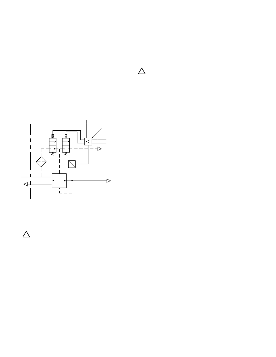
Description
The ERl and ER2 are high flow electro-pneumatic regulators
capable of delivering accurate pressures over a wide range of
flows. The units have a variety of port sizes, ranging from 1/4
inch to 3/4 inch NPT and “G” series threads and use the
convenient Wilkerson 18/28 series modular mounting. The ER
series consists of an integral system of two control valves and
feedback transducer to provide closed-loop control. In addition
the units come with an optional LCD display that displays the
outlet pressure in psig or bar.
The ER series regulators are controlled by either a 0–10 VDC
or 4–20 mA external input signal, or by internal adjustment for
stand- alone operation. The control signal is compared to the
output signal of the internal pressure sensor and the regulator
adjusts the pressure accordingly. The pressure sensor signal
is also an output of 0–10 VDC for external monitoring.