Servicing regulator, Servicing filter element, Parts identification list – Wilkerson B03 User Manual
Page 2: Service kits available
Miniature Filter / Regulator, Miniature Regulators 1/8" and 1/4" Ports
1R602
Servicing Regulator:
Note: See Figure 1, 2, & 3 to aid with this procedure.
1. Unlock the adjusting knob by pulling upward (with the unit in an upright position.)
Then turn adjusting knob counterclockwise until compression of the control spring
has been removed.
2. Remove the bonnet from body. Then remove o-ring (7), piston, lip seal (9), and
control spring to service the bonnet subassembly. Unscrew seat (8) to service the
poppet (17), return spring (5), and /or poppet seal (6).
Note:
On filter / regulator units, the poppet assembly & poppet return spring may be
accessed by removing filter element.
3. Clean old grease from unit and inspect seals for sign of wear (nicks, cuts, and
scratches). Repair kits are available which contain the parts which are typically
replaced.
4. Apply a light film of grease to all seals and sliding surfaces using the grease packet
supplied with repair kit.
Note:
Refer to Figures to determine the correct position and orientation of the various
parts during assembly.
5. Install lip seal onto piston with the lips of the seal facing away from the support
flange. Then insert control spring and piston assembly into bonnet.
6. Place poppet return spring and poppet assembly into bore, followed by poppet
seal and seat.
7. Tighten seat to body from 0.9 to 1.1 Nm (8 to 10 in-lbs) of torque. Tighten bonnet
onto body from 5.6 to 7.3 Nm (50 to 65 in-lbs) of torque.
8. Make sure that the control spring is still uncompressed before turning on the
air supply. Turn on air supply, then slowly adjust the knob clockwise to increase
downstream pressure until the desired pressure has been reached.
9. To decrease regulator pressure setting, always reset from a pressure lower than
the final setting desired. For example, lowering the secondary pressure from 550 to
410 kPa (80 to 60 PSIG) is best accomplished by dropping the secondary pressure
to 350 kPa (50 PSIG), then adjusting upward to 410 kPa (60 PSIG).
10. When the desired secondary pressure setting has been reached, push the
adjusting knob down to lock it.
11. Check for leaks. If leaks occur, shut off the air supply, exhaust system air pressure,
and make necessary adjustments to eliminate leakage.
Servicing Filter Element:
Note: See Figure 1 to aid with this procedure.
1. Unscrew threaded bowl and element holder. Then remove filter element, deflector,
and gaskets.
2. Clean all internal parts, bowl, and body before re-assembling unit. See
Polycarbonate bowl cleaning section.
3. Install deflector, filter element, and gaskets.
4. Attach element holder. Torque 0.9 to 1.4 Nm (8 to 12 in-lbs).
5. To assist with retaining bowl’s o-ring while installing bowl, lubricate the o-ring (with
a mineral based oil or grease). Then place it on the bowl.
6. Screw bowl into body until it is stopped by body; then back off bowl
1/8 turn.
7. Apply pressure to the system and check for leaks. If leaks occur, shut off the air
supply, de-pressurize the system and make necessary adjustments to eliminate
leakage.
If you have questions concerning how to service this unit, contact your local
authorized dealer or your customer service representative.
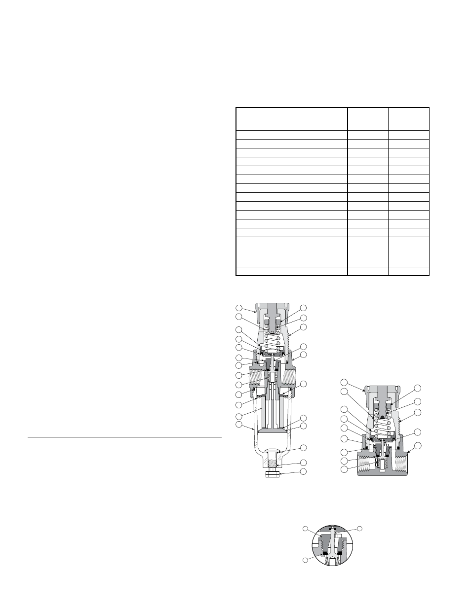
Parts Identification List
Item# Description
1 Bowl (Miniature Filter Regulator)
2 Filter Element (Miniature Filter Regulator)
3 Deflector (Miniature Filter Regulator)
4 O-ring (Miniature Filter Regulator) - bowl to body
5 Poppet Return Spring
6 Poppet Seal
7 O-ring - body to bonnet
8 Seat
9 Lip Seal - piston to bonnet
10 O-ring - piston to poppet (Miniature Regulator & Filter / Regulator
relieving units)
11 Piston (relieving shown)
12 Control Spring
13 Knob
14 Hex Nut
15 Adjusting Screw
16 Bonnet
17 Poppet (Miniature Regulator & Filter / Regulator)
18 Body
19 Gasket (Miniature Filter Regulator) - deflector to body
20 Gasket (Miniature Filter Regulator) - element holder to filter element
21 Element Holder (Miniature Filter Regulator)
22 O-ring (14E) - body to drain
23 Twist Drain (Miniature Filter Regulator)
24 Twist Drain Knob
Service Kits Available
The following service kits contain the appropriate seals and parts necessary for
ordinary field service.
FIGURE 2: Miniature Regulator -
Un-balanced, Relieving Unit Shown
FIGURE 3: Detail of Poppet Seal
6
8
17
13
14
15
16
17
18
12
11
10
8
7
5
6
9
FIGURE 1: Miniature Filter /
Regulator -
Un-balanced, Relieving
Torque:
Finger Tight
6
4
3
9
10
11
7
2
1
8
24
5
12
13
17
14
19
16
20
22
23
21
18
15
Description
Miniature
Filter /
Regulator
Miniature
Regulator
Adsorber
PS452
PS452
5 Micron Element Kit
PS403
N/A
40 Micron Element Kit
PS401
N/A
Metal Bowl w/Manual Drain
PS447B
N/A
Metal Bowl w/Automatic Drain
PS451B
N/A
Mounting Bracket Kit* (plastic ring)
PS417B
PS417B
Mounting Bracket Kit* (aluminum ring)
PS466
PS466
Panel Mount Nut - Metal*
P01531
P01531
Piston & Poppet Kit - Unbal. Rel.
PS426
PS426
Piston & Poppet Kit - Unbal. Non-Rel
PS428
PS428
Polycarbonate Bowl w/Manual Drain
PS404
N/A
Polycarbonate Bowl w/Automatic Drain
PS408B
N/A
Springs: 1-30 PSIG Range
1-60 PSIG Range
2-125 PSIG Range
1-15 PSIG Range
P01175
P01174
P01173
P01176
P01175
P01174
P01173
P01176
Twist Drain Knob
P05117
*Tighten panel mount nut 2.8 to 3.4 Nm (25 to 30 in-lbs) of torque.