Network wiring topology, Vc3xxx led operation – Viconics VTR7300 Installation Manual User Manual
Page 7
7 | PIR Ready VTR7300 Series-Installation Guide
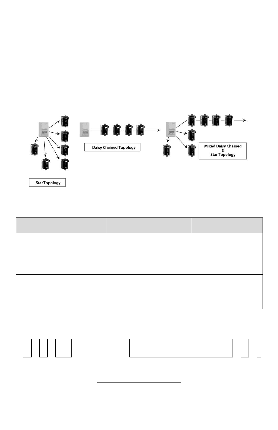
From the VTR73xxA to the first VC3xxxX Relay Pack
Uses existing or new field wires
A minimum of 3 wires are required 14-22 Ga Solid or Stranded. Shield not
necessary.
From the first VC3xxxX to all other slave VC3xxxX Relay Pack(s)
Uses existing or new field wires
A minimum of 2 wires are required 14-22 Ga Solid or Stranded. Shield not
necessary.
Connect only wires #1 Power Common and #2 Tx/Rx Communication
Network wiring topology
VC3
XXX
LED
O
PERATION
LED / Time (Status operation)
Condition of the Status LED
Cause
Solution
2 short blinks
No communication between
the VTR73xxA and the
VC3xxxX relay pack. The
VC3xxxX Relay Pack will
resume
its output “no
communication active” status
Check communication
wiring and or power
cycle the controllers
2 short blinks and a
longer blink
Normal communication
between the VTR73xxA and
the VC3xxxX relay pack.
N/A
0.2
2.5
0.6
0.4
0.0
1.0
5.0 sec
Power On
Online to
VTR73xxA
- VTR8300 Line Voltage Application Guide (23 pages)
- VTR8300 Line Voltage Installation Guide (7 pages)
- VTR8300 Line Voltage User Interface Guide (32 pages)
- VC3000 Line Voltage Installation Guide (8 pages)
- VT8300 Low Voltage Installation Guide (13 pages)
- VT8300 Low Voltage Application Guide (64 pages)
- VT8300 Low Voltage User Interface Guide (45 pages)
- VT8000 Series Device Replacement Guide (7 pages)
- VT8600 Series BACnet Integration Guide (41 pages)
- VT8600 Installation Guide (12 pages)
- VT8600 User Interface Guide (47 pages)
- VT7657 BACnet Integration Guide (First Release 1000 Series) (23 pages)
- VT7657 BACnet Integration Guide (Current Release 5000 Series PIR Ready) (29 pages)
- VT7657 Echelon Integration Guide (22 pages)
- VT7657 Installation Manual (36 pages)
- VT7000 Series Installation Guide (2 pages)
- VT7000 Series Application Guide (27 pages)
- VT8000 Series Uploader Tool (5 pages)
- VT7600 Installation Guide (First Release 1000 Series) (24 pages)
- VT7600 Installation Guide (Current Release 5000 Series PIR Ready) (39 pages)
- VT7600 Echelon Integration Manual (22 pages)
- VT7000 Series PIR cover Installation Guide (2 pages)
- VT7000 Series PIR Application Guide (11 pages)
- VT7682S Application Guide (17 pages)
- VT7682S Installation Manual (19 pages)
- VT7606E Installation Manual (34 pages)
- VT7600W Installation Manual (35 pages)
- VT7600F Installation Manual (29 pages)
- VT7300 Installation Manual (First Release 1000 Series) (17 pages)
- VT7300 Installation Manual (Previous Release 5000 Series PIR Ready) (17 pages)
- VT7300 Installation Manual (Current Release 5000 Series PIR Ready) (33 pages)
- VT7300 (BACnet) Integration Manual (31 pages)
- VT7300 (Echelon) Integration Manual (27 pages)
- VT7300F-2572 Installation Manual (26 pages)
- VT7200 Installation Manual (First Release 1000 Series) (15 pages)
- VT7200 Installation Manual (Previous Release 5000 Series PIR Ready) (15 pages)
- VT7200 Installation Manual (Current Release 5000 Series PIR Ready) (29 pages)
- VC3000 Installation Manual (10 pages)
- VTR7300 Application Manual (28 pages)
- VWA5000W Installation Guide (18 pages)
- VCM7000 Installation Guide (4 pages)
- VWZS Application Guide (40 pages)
- VWZS Integration Guide (70 pages)
- VWZS Engineering Guide Specifications (10 pages)