Terminal, identification and function, Screw terminal arrangement and wiring – Viconics VT7600F Installation Manual User Manual
Page 6
6 | PIR Ready VT7600 Series-Installation Guide
T
ERMINAL
,
I
DENTIFICATION AND
F
UNCTION
Terminal Use
Terminal
Identification
Description
1
– Y2 2
nd
cooling
Y2
Second cooling stage output.
2
– Y1 1
st
cool
Y1
First cooling stage output.
3
– G Fan
G
Fan output.
4
– RC 24VAC hot
RC
Power supply of thermostat, hot side.
5
– C 24VAC com
C
Power supply of thermostat, common side.
9
– AO analog
heat
AO
Analog 0
– 10 VDC heating output.
10
– Auxiliary
output
AUX
Auxiliary output used to disable economizer
minimum position or control lighting during
unoccupied periods.
11
– DI 1
DI 1
Configurable extra digital input. See
parameter section for more information.
12
– DI 2
DI 2
Configurable extra digital input. See
parameter section for more information.
13
– RS
RS
Remote temperature sensor input.
14 - Scom
Scom
Reference input for DI 1, RS, OS & DS.
15 - OS
OS
Outside air temperature sensor input.
16 - DS
MS
Discharge air temperature sensor input.
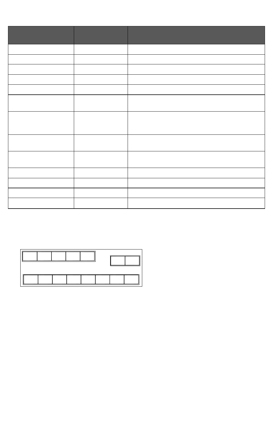
Screw terminal arrangement and wiring
Aux
DI1
DI2
RS
SCom
OS
MS
G
Y1
Y2
C
RC
VT76XXF Controller Terminals
AO
- VTR8300 Line Voltage Application Guide (23 pages)
- VTR8300 Line Voltage Installation Guide (7 pages)
- VTR8300 Line Voltage User Interface Guide (32 pages)
- VC3000 Line Voltage Installation Guide (8 pages)
- VT8300 Low Voltage Installation Guide (13 pages)
- VT8300 Low Voltage Application Guide (64 pages)
- VT8300 Low Voltage User Interface Guide (45 pages)
- VT8000 Series Device Replacement Guide (7 pages)
- VT8600 Series BACnet Integration Guide (41 pages)
- VT8600 Installation Guide (12 pages)
- VT8600 User Interface Guide (47 pages)
- VT7657 BACnet Integration Guide (First Release 1000 Series) (23 pages)
- VT7657 BACnet Integration Guide (Current Release 5000 Series PIR Ready) (29 pages)
- VT7657 Echelon Integration Guide (22 pages)
- VT7657 Installation Manual (36 pages)
- VT7000 Series Installation Guide (2 pages)
- VT7000 Series Application Guide (27 pages)
- VT8000 Series Uploader Tool (5 pages)
- VT7600 Installation Guide (First Release 1000 Series) (24 pages)
- VT7600 Installation Guide (Current Release 5000 Series PIR Ready) (39 pages)
- VT7600 Echelon Integration Manual (22 pages)
- VT7000 Series PIR cover Installation Guide (2 pages)
- VT7000 Series PIR Application Guide (11 pages)
- VT7682S Application Guide (17 pages)
- VT7682S Installation Manual (19 pages)
- VT7606E Installation Manual (34 pages)
- VT7600W Installation Manual (35 pages)
- VT7300 Installation Manual (First Release 1000 Series) (17 pages)
- VT7300 Installation Manual (Previous Release 5000 Series PIR Ready) (17 pages)
- VT7300 Installation Manual (Current Release 5000 Series PIR Ready) (33 pages)
- VT7300 (BACnet) Integration Manual (31 pages)
- VT7300 (Echelon) Integration Manual (27 pages)
- VT7300F-2572 Installation Manual (26 pages)
- VT7200 Installation Manual (First Release 1000 Series) (15 pages)
- VT7200 Installation Manual (Previous Release 5000 Series PIR Ready) (15 pages)
- VT7200 Installation Manual (Current Release 5000 Series PIR Ready) (29 pages)
- VC3000 Installation Manual (10 pages)
- VTR7300 Installation Manual (25 pages)
- VTR7300 Application Manual (28 pages)
- VWA5000W Installation Guide (18 pages)
- VCM7000 Installation Guide (4 pages)
- VWZS Application Guide (40 pages)
- VWZS Integration Guide (70 pages)
- VWZS Engineering Guide Specifications (10 pages)