Caution, Vt8600 series bacnet, Integration manual – Viconics VT8600 Series BACnet Integration Guide User Manual
Page 26: Eol resistor eol resistor eol resistor sc, Repeater eol resistor eol resistor repeater
VT8600 Series
BACnet
®
Integration Manual
26
Viconics Technologies Inc.
|
9245 Langelier Blvd.
|
St.-Leonard
|
Quebec
|
Canada
|
H1P 3K9
|
Tel: (514) 321-5660
|
Fax: (514) 321-4150
028-0437-00
www.viconics.com
|
March 2015
©
2
01
5 V
ic
onic
s T
ec
hno
lo
gi
es
Inc
. A
ll r
ig
ht
s r
ese
rv
ed
.
13-COM +
14-COM -
VTR83xxA
Terminal Controller
13-COM +
14-COM -
VTR83xxA
Terminal Controller
To others
To others
EOL
Resistor
EOL
Resistor
EOL
Resistor
SC
Supervisory
Controller
Repeater
EOL
Resistor
EOL
Resistor
Repeater
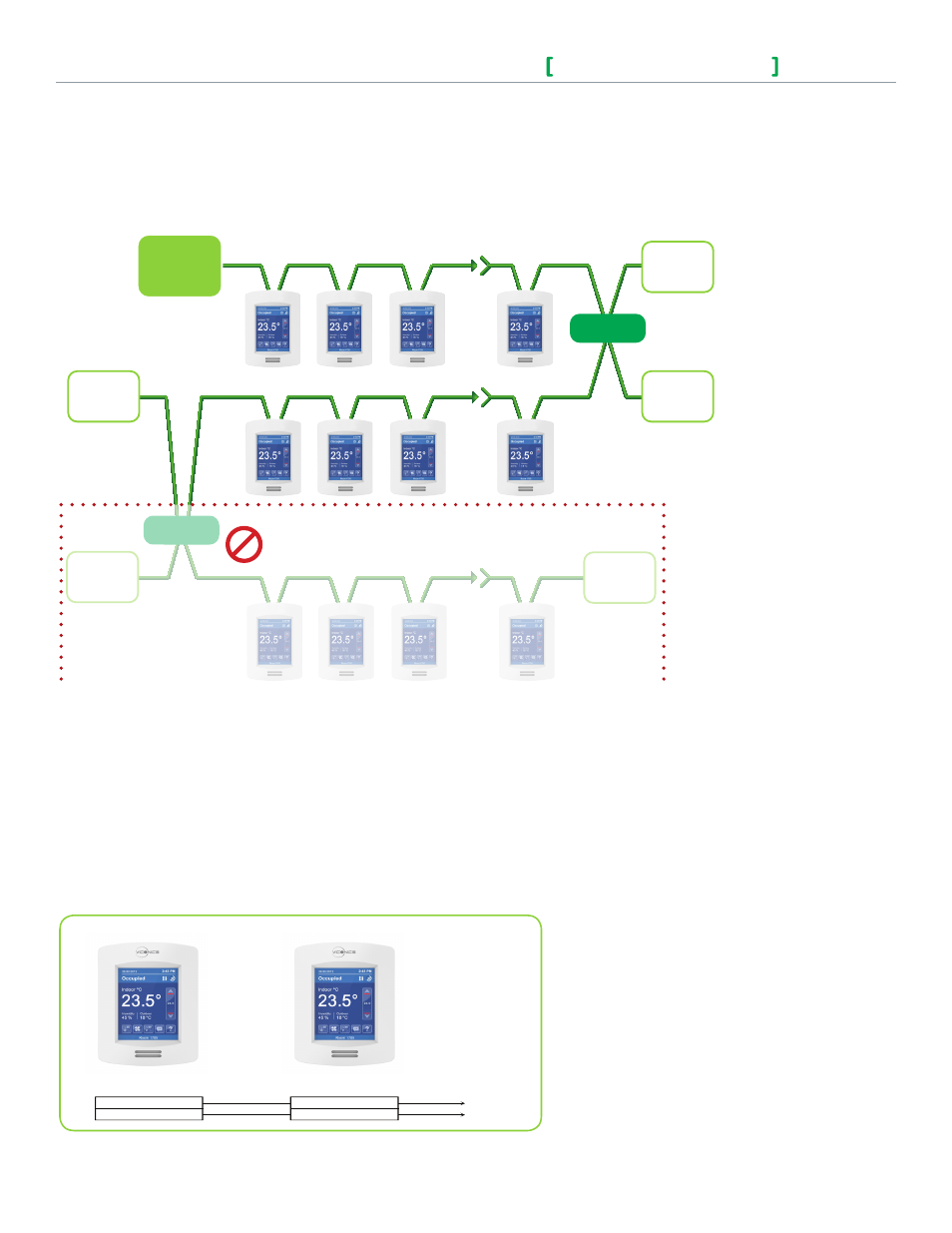
CAUTION:
DO NOT ADD A SECOND REPEATER IN SERIES
MS/TP network must be properly terminated. For daisy chain configurations, you must install an EOL resistor
at each end of the daisy chain. Depending on your MSTP network configuration, the resistance value of the
EOL resistor may change. Viconics devices are installed at both ends of the MSTP network. Also, a 120 Ohm
resistor should be installed at each end.
A Viconics device is installed at one end of the MSTP network and a 3rd party device is installed at the other
end. Make sure you install an End-Of-Line resistor value that matches the 3rd party devices instructions
regarding its EOL resistor value. Any 3rd party devices are installed at both ends of the MSTP network.
Network Adapter
Figure-6 Incorrect Repeater Use in an EIA-485 Network
BACnet
®
Communication Wiring (if applicable)
The ideal configuration is to daisy chain the repeaters to the main panel. From each of these repeaters, a
separate daisy chain branches off. Figure 5 demonstrates a valid use of repeaters in an EIA-485 network.
Do not install repeaters in series as this may result in network reliability problems. Incorrect use of a repeater
in an EIA-485 network is illustrated below in Figure 6.
Figure-7 MS/TP Connections