Top Flite Wristcrat User Manual
Page 8
D 13. Remove ply die-cut part F-6 from its sheet. This is
the forward, bottom fuselage sheet which is
meant to fit from the cross brace just installed, for-
ward to the noseblock. Clean-up its edges with a
sanding block. F-6 can now be glued in place using
weights or tape to hold it (note that its rear edge is
glued halfway across the width of the cross brace;
use a scrap piece of balsa to clean out any oozing
glue from beneath this edge). Using the 1/16" x 3"
balsa sheet stock provided, finish sheeting the
fuselage bottom from the rear edge of F-6, aft to
the end of the fuselage - as shown this sheeting is
applied cross grained. Once the sheeting is in
place and dry, use your sanding block to smooth
all of the edges (balsa sheeting and F-6) flush with
the fuselage sides. Now clear out the finger hole
described by F-5, using sandpaper to smooth the
edges. The last thing you may wish to do on the
bottom of the fuselage is to drill a hole, back
toward the leading edge of the fin location, to pro-
vide an exit for your antenna. On our prototypes we
angled this hole forward and lined it with a short
length of plastic tubing.
D 14. Now trial fit your wing to the fuselage. Make sure
the wing is centered and that the leading edge is
up against F-3. Holding these two structures
together, observe the fit between the bottom of the
wing and the wing saddle area. It may be
necessary to slightly bevel the tops of the fuselage
sides and F-2 doublers to get a snug fit; do this
now. Once you're satisfied with the wing/fuselage
fit, you're ready make the hold-down system.
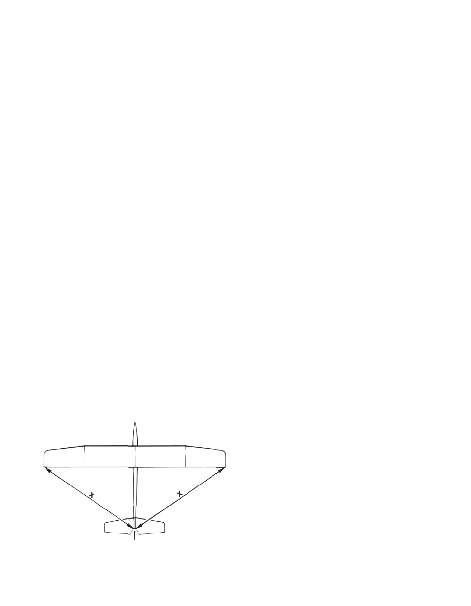
Again place the wing on the fuselage and use
weights to hold it firmly in position. Make sure that
the wing is squarely in position on the fuselage by
taking wingtip-to-tailpost measurements as
shown in the diagram ("X" should equal "X").
Locate the 3/16" dia. dowel from the parts bag. A
3/16" dia. hole must now be drilled through F-3 (see
mark) and into the wing's center W-1 ribs, to a
depth of 1-7/16", measured from the front face of
F-3. Measure this depth on y o u r drill bit and note it
with a strip of tape. Once the hole is drilled, remove
DISTANCES "X" and "X"
MUST BE EQUAL
the wing from the fuselage and trial-fit the 3/16" dia.
dowel in place. Use sandpaper to slightly round
the front edge of the dowel. Now glue the dowel in
place in the wing (clean-off any oozing glue). Once
dry, again fit the wing to the fuselage and use
weights to hold it in place, as before. The rear
nylon bolt hold down system is now made. Start by
drilling a hole, with a #29 drill bit, through the
wing's trailing edge and through the 1/8" ply wing
bolt plate at a slightly forward angle (see plans).
Remove the wing from the fuselage. Enlarge the
hole in the wing's trailing edge to allow the 8-32
nylon bolt to slip through to the head. Now using
either an #8-32 tap or an 8-32 bolt (metal), tap the
threads into the hole made in the ply wing bolt
plate. Once the threads have been cut we suggest
giving them a very thin coat of instant CA glue and
again running the tap through them. This
toughens the threads in the plywood. Re-fit the
wing to the fuselage and bolt it in place to again
check the fit. Note that about 7/8" of the length of
the nylon bolt (1-1/2" supplied) can be trimmed off.
Remove the wing from the fuselage.
D 15. Use a flat sanding block and light sandpaper to
carefully sand the top of the fuselage, from F-3 for-
ward across the top of the noseblock. Use care
here as we want the forward hatch to fit nicely.
From your parts, locate and remove the 3/8" x 2" x
10" length of balsa. Again using your sanding
block, bevel-sand one end of this block to fit
perfectly against the forward face of F-3 when held
in place on top of the fuselage. As shown on the
plans, the forward end of the radio hatch is now cut
at the angle shown. Once the bevel cut has been
made, use the sanding block to lightly clean-up
each end of the cut, set aside the hatch part for a
moment. On the remaining length of block,
measure about 1-3/4" forward from the bevel cut
and cut this piece off. This piece then becomes the
forward "lip" for the radio hatch. Use tape to hold
the radio hatch in place to the top of the fuselage,
against F-3. Apply a small amount of glue to the
bottom of the forward block and glue it in place to
the top of the fuselage and noseblock, matching
the bevel on the front of the radio hatch block, thus
ensuring a nice fit between these two blocks. Un-
tape and remove the radio hatch block. Locate and
remove the ply F-4 hatch "lip" from its die-cut
sheet. F-4 can now be glued to the forward, bottom
surface of the hatch block with 3/16" of its forward
end protruding, thus providing a fit beneath the
forward block just installed and preventing shif-
ting from side-to-side. As shown on the plans, the
rear face of the radio hatch block will need a slight
amount of routing out to allow the wing's hold-
down dowel to clear; do this now. Once satisfied
use a couple drops of glue to l i g h t l y tack-glue the
radio hatch in place for shaping.
D 16. Remember that V length of 1/16" I.D. aluminum
tubing that you were asked to save back when you
built your stabs? Locate it now, we're going to use
it. With a 3/32" drill bit, finish the hole through the fin
(the stab pivot hole). Cut a 1/4" length of aluminum
8