Top Flite Wristcrat User Manual
Page 6
D 1. Remove the two fuselage sides from their die-cut
sheet. Tape, pin or clamp them together and use a
sanding block to lightly sand their edges, thus
matching them exactly. Now lay one of the
fuselage sides directly over the side view on the
plans and accurately mark the location of the F-3
lite-ply former. Also mark the location of the end
of the top 1/8" sq. balsa longeron at the leading
edge of the fin — this will be at an angle, use a
straight edge. Lastly, mark the location of the for-
ward end of the bottom 1/8" sq. longeron, where it
butts against the noseblock. Duplicate these
marks on the remaining fuselage side —
remember that you need a right and a left
fuselage side!
D 2. Glue the two F-2 balsa doublers in place on the in-
side faces of each fuselage side, matching its top
contours to those of the fuselage sides. Glue the
top and bottom 1/8" sq. balsa longerons in place
after first trimming their ends to fit the marks
made earlier. Remove the fuselage sides from
your work surface and pin, tape or clamp them
together again. Use your sanding block to once
again make sure they are identical. While they're
together, check the trimmed ends of each
longeron to be sure they are matched accurately.
Set these aside for now.
D 3. Using the 3/16" sq. and 3/32" x 3/16" balsa stock provid-
ed, build the fin frame directly over the plans.
Take your time and ensure that each of the re-
quired joints is accurate and well-matched.
Remove the frame from your work surface and
use a sanding block to lightly smooth out the
sides and edges. Remove one of the T-1 fin sheets
from its die-cut sheet. This can now be glued in
place to the right side of the fin frame, as shown
on the plans. Do this operation accurately and
with a minimum amount of glue.
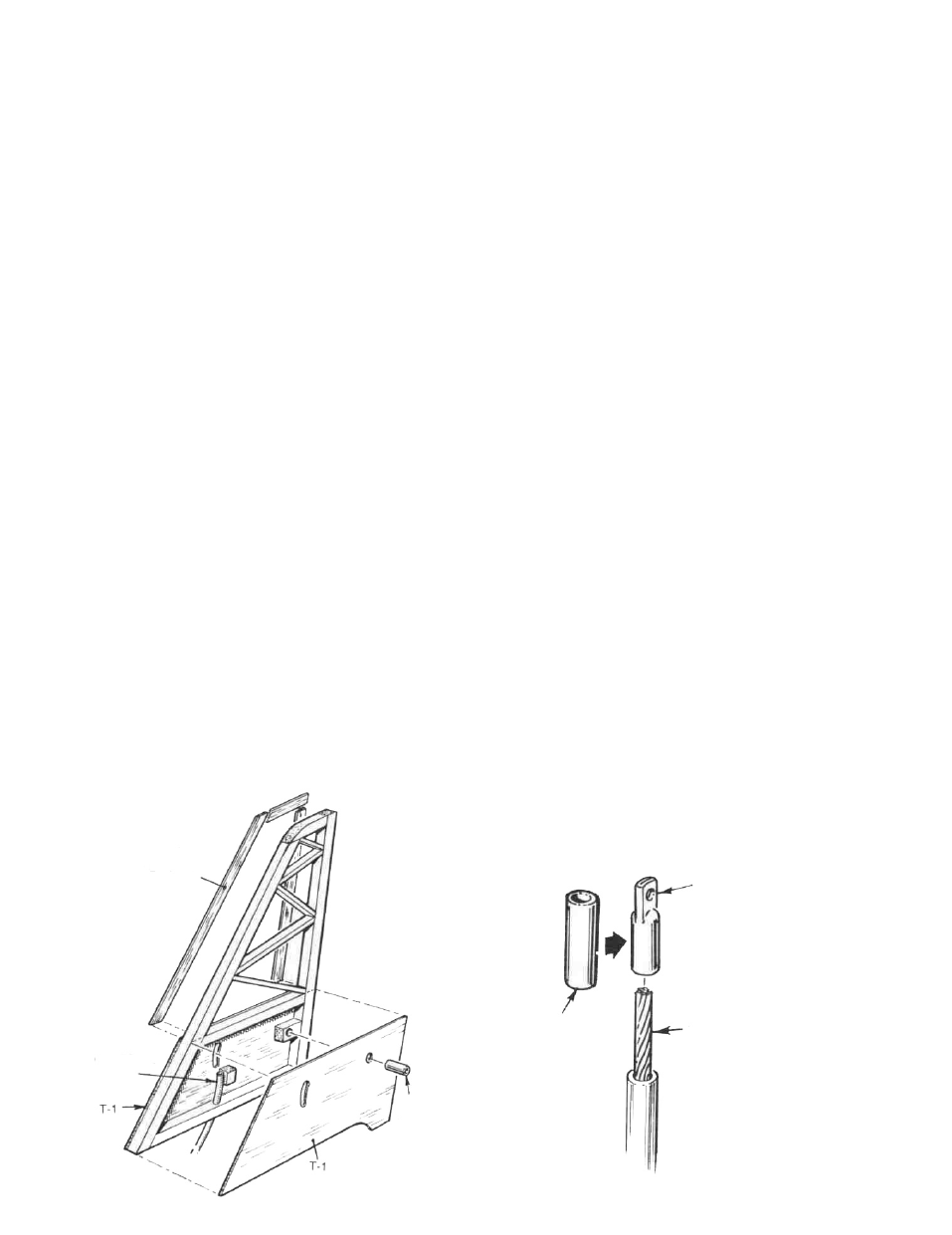
D 4. The right side of the fin frame, outer 3/16 "edges on-
ly, is now capped with 1/32 " x 3/16" strips cut from the
1/32" X 3/16" BALSA
LAMINATED EACH SIDE
OF FRAME
CABLE GLUED TO
BALSA BLOCK
1/16" I.D.
ALUMINUM
TUBE
open, center area of die-cut sheet #RC-35-5. This
carries through the increased thickness of the fin
created by the T-1 fin sheet. Note the "+" mark
toward the rear of the T-1 fin sheet. Use a 3/32 "drill
to accurately make a hole at this mark. This hole is
referred to as the stab pivot hole. As shown on the
plans, glue a short length (about V will do) o f 3/16"
balsa stock directly over the 3/32" dia. hole just drill-
ed through T-1.
D 5. Take the right fuselage side and pin or weight it in
place carefully over the plan. Place the fin
assembly on the fuselage side, at the rear to check
its fit and trim carefully, if needed. Place a scrap
piece o f 3/32" stock underneath the fin frame, above
the fuselage side, to bring the fin level. Carefully
glue the fin frame assembly to the fuselage side-
pin or weight in place and allow to dry.
D 6. From your kit box locate and remove one of the
braided metal drive cables and one of the outer
cable housing tubes. Use a piece of sandpaper to
lightly scuff the outer surface of the plastic tube.
As shown on the plans, the stabilizer cable drive
tube is going to be glued directly to the right
fuselage side and up into the lower fin, directly
beneath the oval stab drive hole in T-1. Position the
forward end of the stab drive tube just ahead of the
F-3 former location and glue it in place to the right
fuselage side, just beneath the F-2 doubler and
about 1-1/2" back from the F-3 location. (An
adhesive such as Pacer's Slo-Zap CA is great for
this operation.) Repeat this procedure all the way
back to just beneath the fin, noting that the stab
drive tube gently arcs down to the fuselage bottom
as it is positioned rearward. Before making the
bend up to the oval hole in T-1, load the tube with
the inner braided cable. Now make the bend up to
the hole and hold this assembly in position. Try
moving the cable back and forth; it should move
easily without binding. Once satisfied, glue the
short length o f 3/16" sq. balsa in place as shown to
hold the tube and then glue the tube to this block.
Use a razor blade to trim off the tube end after re-
moving the cable.
BRASS TUBE
FLATTEN END THEN DRILL
1/16" DIA. HOLE
STABILIZER CONTROL CABLE.
SOLDER INTO BRASS TUBE
6