Top Flite Wristcrat User Manual
Page 7
D 7. As shown on the plans, the stab drive fitting itself
is nothing more than a short length of 1/16" I-D.
brass tubing (
1
1/2" provided) which has about 1/8" of
it's length flattened in a vise. This "flat" is then
drilled with a 1/16" dia. hole. The other end of this
tube is trimmed in length to leave only about 1/8"
left that is still "tube". This fitting is then soldered
to the end of the stab drive cable. Do all of this now.
Handy Hint: Insert one of the 1/16" dia. M.W.
stabilizer pins provided, into this piece of tubing,
almost to the end and then flatten the tubing in a
vise. The music wire pin will keep the tubing round.
D 8. Now install the rudder drive tubing on the left
fuselage side. As shown, this tubing exits the
lower rear of the fuselage side through a heavily
angled hole that must be drilled. A sharpened
piece of tubing will work well for this step. Like the
elevator tubing, the rudder housing tube is glued in
place along the fuselage side at 1-1/2" intervals.
Use a razor blade and then your sanding block to
smooth the area of tubing exit on the outside of the
fuselage. Don't worry about the stab and rudder
tubing that is loose up front, we'll nail these down
later.
questions, take the time now to trim the ends of
the longerons and/or the F-2 doublers to correct
the problem. Once satisfied, glue the nose block in
place and clamp or tape the fuselage sides
together at the nose until dry. When it is, use your
sanding block again to smooth out the
fuselage/nose block fit, top and bottom.
NOSE BLOCK
D 9. Now glue the remaining T-1 fin side in place on the
left side of the fin, with the stab drive cable and fit-
ting in place. Glue 1/32 " 3/16"" caps on the left side of
the fin frame, just as you did on the right. Use your
sanding block to smooth this structure. Now trial-
fit the left fuselage side to the right, paying par-
ticular attention to the fit of the fin. This should be
accurate and close-fitting. Once satisfied, the left
fuselage side can be glued in place to the fin and
right side—the glue joints should be at the top and
bottom longerons 1/2" ahead of the fin's leading
edge back to and including the left T-1 fin side. Ac-
curately match the fuselage sides, weight and/or
pin this structure to your work surface and allow to
dry.
D 10. Ply fuselage former F-3 should now be trial-fitted
in place (just move the loose ends of the rudder
and stab tubes out of the way). Make sure this
former fits well, trim if necessary. Take one of the
servos that you plan to use and hold it in place on
the inside of the fuselage, about where it will be
mounted. Note the location for the two drive tubes
on F-3 (these should be lined-up with the servo's
output arm. Remove F-3 and either drill a hole or
slot the former to accept the two tubes. You now
can glue F-3 in position at the marks made earlier
on each of the fuselage sides. We suggest using
something like 5-minute epoxy for this operation
since you may need a moment or two for position-
ing. We also suggest that you accurately position
the entire structure over top view on the plans and
use weights or pins to ensure that the whole thing
is kept straight!
D 11. Trial-fit the balsa nose block in place and pinch the
fuselage sides together as if you were gluing it in
place. How does it fit? Everything square as it
ought to be? When viewing the structure head-on,
is it straight? If the answer is no to any of these
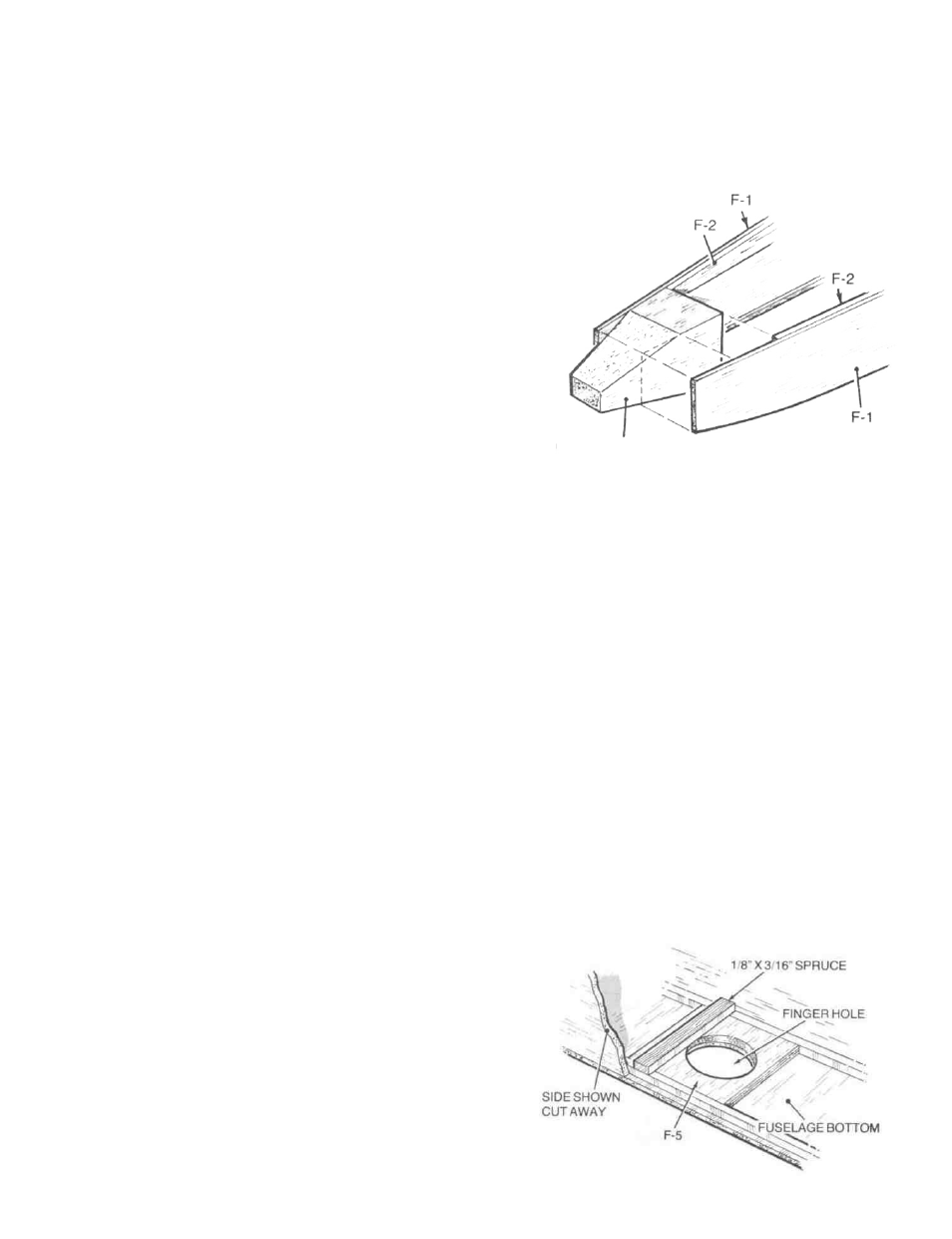
D 12. Locate the 1/8" ply wing-bolt plate from your parts
bag. Trial-fit this part in place at the location
shown on the plans (beneath the wing's trailing
edge). Trim if needed. Once satisified, glue this
plate in place against each fuselage side and up
against the bottom of the F-2 doublers. Locate and
remove the die-cut F-5 fingerhole reinforcement
piece. Trial-fit F-5 in place flush with the bottom
fuselage longerons and directly beneath the 1/8"
ply bolt plate just installed. Once satisfied with the
fit, glue F-5 in place, between the bottom
longerons and flush with the fuselage sides. Now
cut a 1-3/8" length of 1/16" x 3/16" spruce spar stock. As
shown on the plans, this part is now glued in place
on top of F-5, between the fuselage sides, at the
forward edge of the fingerhole cut-out. This part
serves to reinforce F-5 against undue wear during
repeated hand-launches. Lastly, cut and glue the
1/8" x 3/16" balsa cross brace in place. As shown on
the plans, this brace fits between the bottom
fuselage longerons, just behind the receiver loca-
tion. Use your sanding block to now lightly smooth
the fuselage bottom prior to sheeting.
7