Top Flite Wristcrat User Manual
Page 5
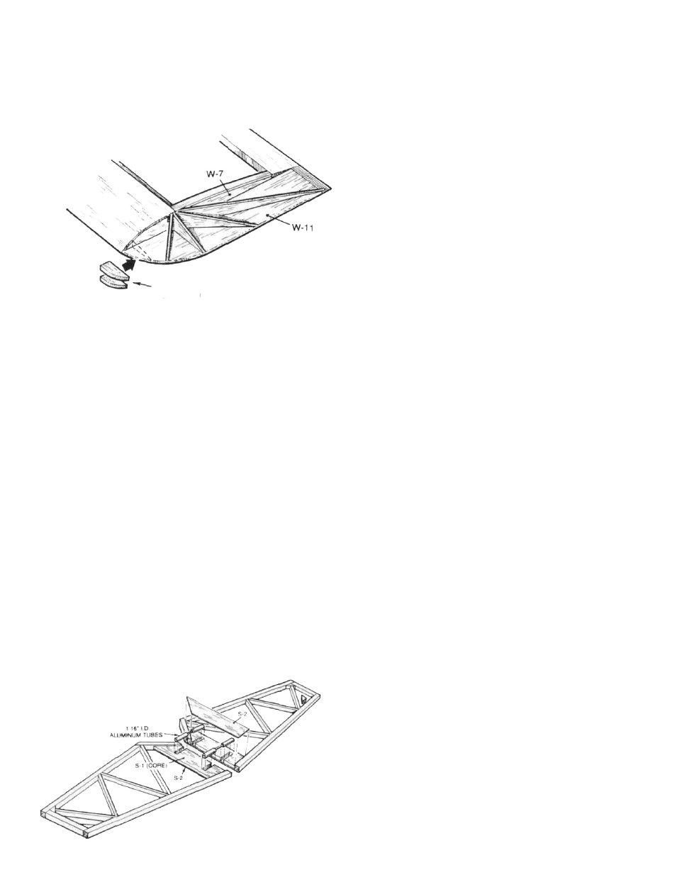
leading edge of the wingtip and glue these in
place. From the remaining 1/16" balsa sheet provid-
ed in your kit, cut, fit and glue in place the wing tip
braces as shown on the plans. You may elect to
add these only to the top, which will work.
However, on our prototypes we added these
braces top and bottom and have yet to break a tip.
.1/8" BALSA FILL
TOP AND BOTTOM
The completed wing structure should now be carefully
sanded to final shape including the leading edges. Make
every attempt to render the wing as smooth and as
uniform as possible.
Ply die-cut part F-12, wing bolt reinforcement, can now
be glued in place on the wing's center section at the trail-
ing edge, as shown. With the exception of the front and
rear fuselage/wing fairings, the wing should now be
complete.
STABILIZERS/RUDDER CONSTRUCTION
STABILIZERS
D 1. Remove the four 1/32" S-2's and both of the 3/32" S-1's
from their respective die-cut sheets. These are
the stab cores (S-1's) and stab core caps (S-2's).
From your parts bag, locate the single 3" length of
1/16" I.D. aluminum tubing. Measure and cut-off
two, 1-1/4" lengths of this tubing. Use a single edge
razor blade and a rolling motion on a hard surface
to do this. Save the remaining 1/2" length. Note the
cross-grain marks in the S-1 cores, these are the
locations for two lengths of aluminum tubing that
you just cut. Use a straight edge and a sharp #11
blade to clear-out a 3/32" slot at these marks to
allow the nesting of the two pieces of tubing. Take
care in cutting these slots to maintain their
parallelism.
D 2. Glue t w o o f t h e S - 2 c a p s t o t h e b o t t o m o f e a c h S - 1 ,
carefully lining-up their edges one to the other.
Use sandpaper to lightly rough-up the two 1-1/4"
lengths of aluminum tubing. Place the two S-1/S-2
structures together on your building board with
their inboard edges touching and the slots lined
up. Glue the two lengths of aluminum tubing in
place in the slots being careful to keep glue out of
the tube ends. Wipe off any excess glue that may
ooze up. Now glue the two remaining S-2 parts to
the tops of the S-1's, aligning their edges, weight
to keep these flat and allow to dry. If you're using
Pacer Slo-Zap, this will be very fast. Cut the two
structures apart, at the center, using a sharp razor
blade or a fine-toothed X-acto-type saw. Clean-up
the ends of the aluminum tubing with your #11
blade. Holding the two structures together, one
on top of the other, use your sanding block to
sand each of the edges flat.
D 3. Locate the two 1/16" dia. x1-1/2" steel pins from your
parts bag. Clean the ends of each of these with a
grinder or carbide cut-off wheel and trial-fit them
into the aluminum tube nests in each of the stab
core assemblies. You should be able to lay this
joined assembly directly over the stab plans and
they should match accurately. Trim as needed to
achieve this. Once satisfied, weight or pin the
wire-joined core assemblies in place over your
plans (protect the plans with a piece of Monokote
backing) and build the balance of each stab half
onto each stab core assembly using the 3/16" sq.
and 3/32" x3/16" balsa stock provided.
D 4. Once the stab halves are finished, remove them
from your work surface and use your sanding
block to first sand the top and bottom surfaces of
each flat and then to carefully "airfoil" them to
the cross-sections shown on the plans. Use care
to not sand these structures to thin, we don't
want them weak. Set these assemblies aside for
now.
RUDDER
D 1. The rudder is built directly over the plans, using
the 3/16" sq. and 3/32" x 3/16" balsa stock provided, just
as the stab halves were.
D 2. Remove the completed rudder from your work
surface and use your sanding block to smooth
the sides as well as the edges. As shown on the
plans, the top, leading edge and bottom of the
rudder, on each side, is capped with 1/32" x V
balsa strips, cut from the RC-35-5 die-cut sheet.
This renders the rudder the same thickness as the
fin.
The final sanding of the rudder and the beveling of its
leading edge, for hinging purposes, will be done later in
Final Assembly.
FUSELAGE/FIN CONSTRUCTION
Note that the fuselage and fin, with it's stabilizer drive,
are constructed in the following set of instructions, as a
finished, single unit.
5