Installing monokote hinges – Top Flite Wristcrat User Manual
Page 11
Cover these structures just as you normally would; bot-
tom first, followed by the tops (in the case of the stab
halves). But do not shrink the covering yet. Make sure all
of the outer framework of these pieces is adhered to with
the Monokote. Next, cut a couple of 7" - 9" lengths of
straight, stiff spruce stock; something like1/8"x1/4" will do
nicely. Using three office-type paper clamps, mount and
clamp one length of spruce on each side of the trailing
edge of the piece you're working on. The spruce won't
hurt the structure and the clamps ensure that the trailing
edge will retain it's shape. Now use your Top Flite heat
gun or iron to shrink the covering equally on both sides
(be sure the vent holes are cleared out). Let the structure
cool and then remove the clamps and spruce. You
should find that everything did indeed stay straight.
Lastly, clear out all of the required holes; rudder drive
tube, rudder horn slot, stab drive and pivot holes, etc.
Note that we've not indicated any kind of hold down
method for the radio hatch block. On our prototypes this
was not necessary because of the closeness of the fit
after covering. If yours does not fit that well, a little piece
of tape is all that's needed.
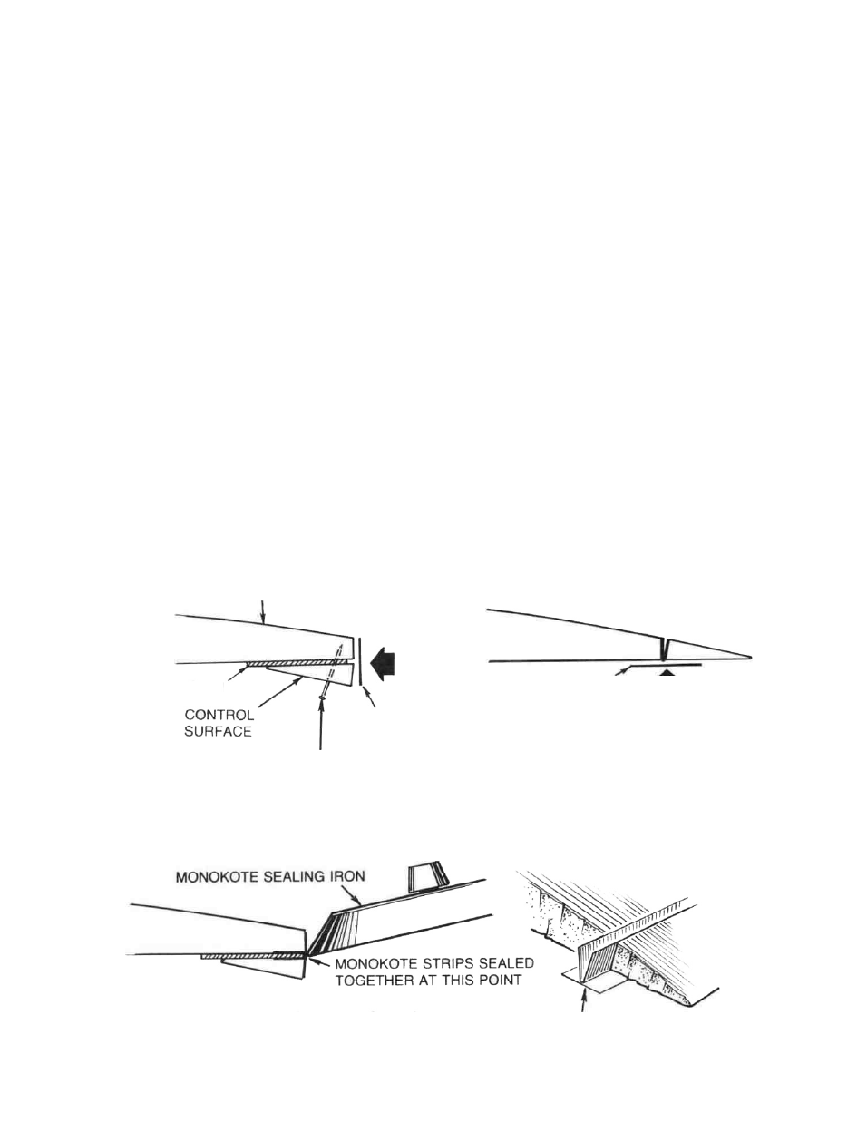
In the interest of aerodynamic efficiency, light weight
and simplicity, we strongly suggest that you hinge your
rudder (and flaps, if you have them) with Monokote as
shown in the drawings provided.
RADIO INSTALLATION
Before installing your servos, make sure that they run in
the right directions. If you have servo reversing capabili-
ty, this is a simple task. Install the servos in the fuselage
on the rails provided earlier.
From your parts bag, locate the 1-1/2" length of .038 I.D.
brass tubing. This material will be cut up to provide
solder connections between the drive cables and the
soft wire paper clip connectors. We recommend the use
of a good quality flux and solder when perform ing the re-
quired solder joints; Harris's Stay-Clean Flux and silver
solder are great products for this operation.
Drill a 1/32" dia. hole through the rudder horn to accept the
paper clip drive wire. Cut off about 1/4" of the brass tubing
connector material and clean out each of it with your #11
blade to accept the cable and paper clip ends. Cut off the
required length of paper clip wire (see plans) to make the
connection to the rudder horn and bend one end into a
"Z" bend. Slip the brass connector halfway onto the
drive cable end and the paper clip wire into the other end
of this connector. Sweat solder the three pieces
together, using a minimum of solder. Slip the opposite
end of this drive cable into the rudder tube and feed it's
length through the fuselage and into the servo compart-
ment — don't cut off the excess cable yet. Attach the
rudder horn to the "Z" bend and carefully glue the horn
into the slot previously provided.
INSTALLING MONOKOTE HINGES
WING, FIN, ETC.
PIN THROUGH CONTROL
SURFACE TO PREVENT
MOVEMENT
1/32" SHIM
MONOKOTE
MONOKOTE IRONED TO
INSIDE FACES
IRON SECOND MONOKOTE STRIP
TO OUTSIDE FACE
MONOKOTE HINGE
11
SEAL MONOKOTE STRIPS
TOGETHER. KEEP SHIM PRESSED
AGAINST SEAM AS BACK UP
WHILE SEALING.