Top Flite P-47 D Thunderbolt('76) User Manual
Page 5
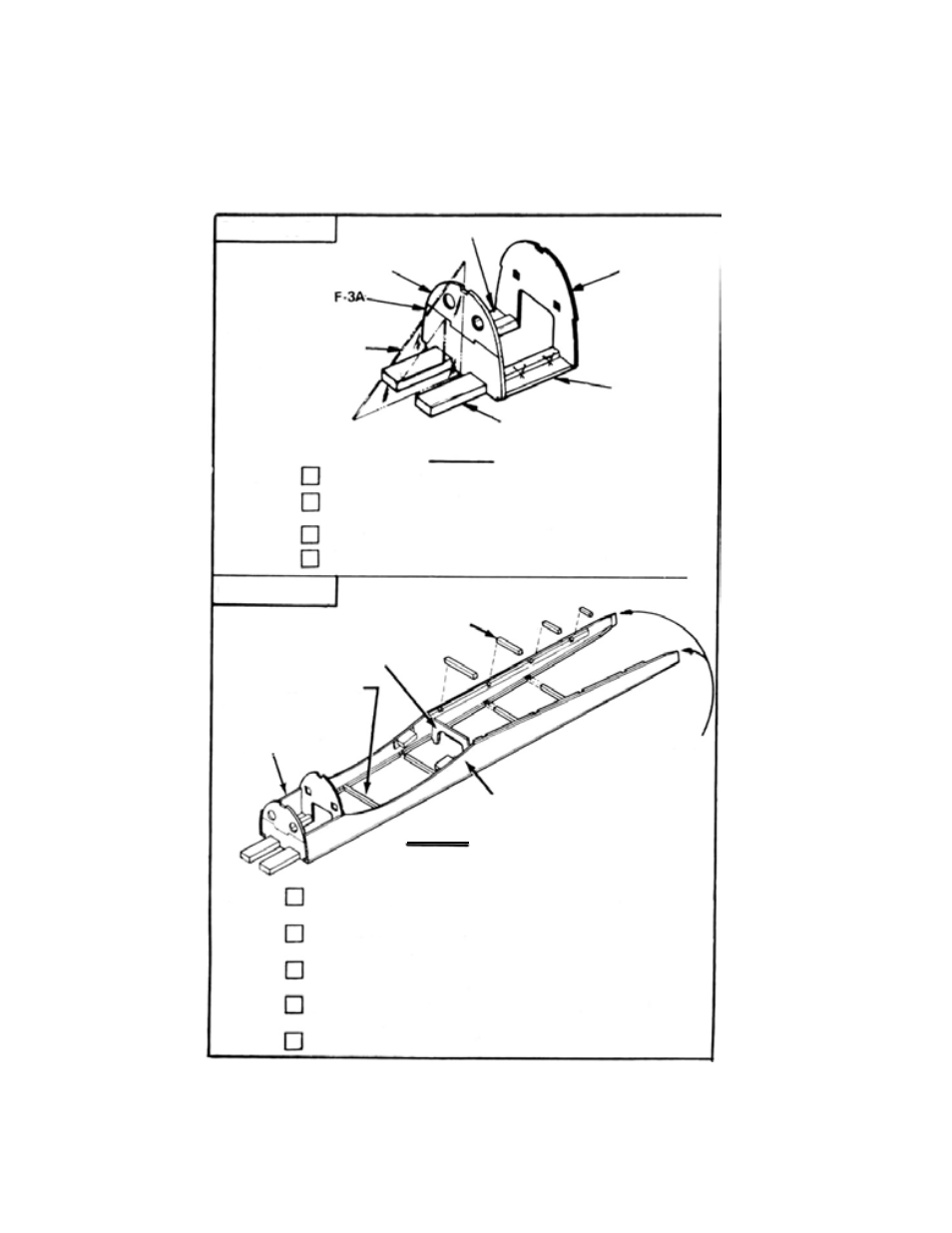
HARDWOOD MOTOR MOUNTS
FIG. 2
3
3
Using bottom view of plans, cut 1/4 SQ. bulkhead spacers from
1/4 x 1/4 x 36 balsa strips.
Glue MOTOR MOUNT ASSEMBLY to fuselage sides over
bottom view of plans.
Starting with bulkhead spacer for F-8, glue and pin spacers in
place, working toward rear.
Glue F-17 (ply) in place. (Check
plans for position). Hold
fuselage sides together with tape if necessary.
Trim rear, glue, and clamp together.
STEP
FIG. 3
FUSELAGE SIDE
TRIM TO 1/8" EACH
SIDE, GLUE, AND
CLAMP TOGETHER
BULKHEAD SPACER
FOR F-8
MOTOR MOUNT
ASSEMBLY
1/4" SQ. SPACERS
F-17 (PLY)
F U S E L A G E
Glue F-3A and F-3B together.
Pin F-5 spacers over bottom view of plans BETWEEN F-3AB
and F-7.
Glue motor mounts to the two F-5's.
Glue F-3AB assembly and F-7 (ply) vertical in position.
S T E P
2
FUSELAGE
F-3B
F-5
F-7 (PLY)
USE TRIANGLE OR
SQUARE TO CHECK
ALIGNMENT.
F-5SPACERS
- TOPA0300 (56 pages)
- TOPA0210 (32 pages)
- TOPA0500 (68 pages)
- TOPA0215 (42 pages)
- TOPA0410 (62 pages)
- TOPA0101 (44 pages)
- TOPA0120 (56 pages)
- TOPA0415 (66 pages)
- TOPA0135 (56 pages)
- TOPA0400 (60 pages)
- TOPA0110 (60 pages)
- TOPA0140 (64 pages)
- TOPA0310 (60 pages)
- TOPA0160 (66 pages)
- TOPA0965 (32 pages)
- TOPA0906 (36 pages)
- TOPA0951 (36 pages)
- TOPA1000 (12 pages)
- TOPA0704 (48 pages)
- TOPA0706 (36 pages)
- TOPA0705 (40 pages)
- TOPA0703 (36 pages)
- TOPA0700 (48 pages)
- TOPA0708 (36 pages)
- TOPA0712 (40 pages)
- TOPA1025 (16 pages)
- TOPA1005 (24 pages)
- TOPA0970 (32 pages)
- TOPA0955 (36 pages)
- TOPA0950 (32 pages)
- TOPQ8402 (2 pages)
- TOPQ8401 (2 pages)
- TOPQ8404 (1 page)
- TOPQ8407 (1 page)
- TOPQ7899 (3 pages)
- TOPQ8405 (1 page)
- TOPQ8410 (1 page)
- TOPQ8406 (1 page)
- TOPQ8414 (2 pages)
- TOPQ5700 (8 pages)
- TOPQ7903 (2 pages)
- TOPQ7901 (2 pages)
- TOPQ7902 (2 pages)
- TOPQ8412 (2 pages)
- TOPR2420 (7 pages)