Top Flite TOPA1020 User Manual
Page 6
❏
7.
Roughen up the por
tions of the joiner wire that
fit into the flaps with sandpaper
.
Clean the wire with
denatured alcohol.
Mix a small batch appro
ximately
7.5 cc [1/4 oz] of 30-min
u
te epo
xy
.
Use a piece of
wire or a toothpic
k
to apply epo
xy to the holes and
g
roo
v
es in the flaps f
o
r the joiner wire
.
Coat the
matching halv
es of the joiner wire with epo
xy
, and
then inser
t it into the flaps
.
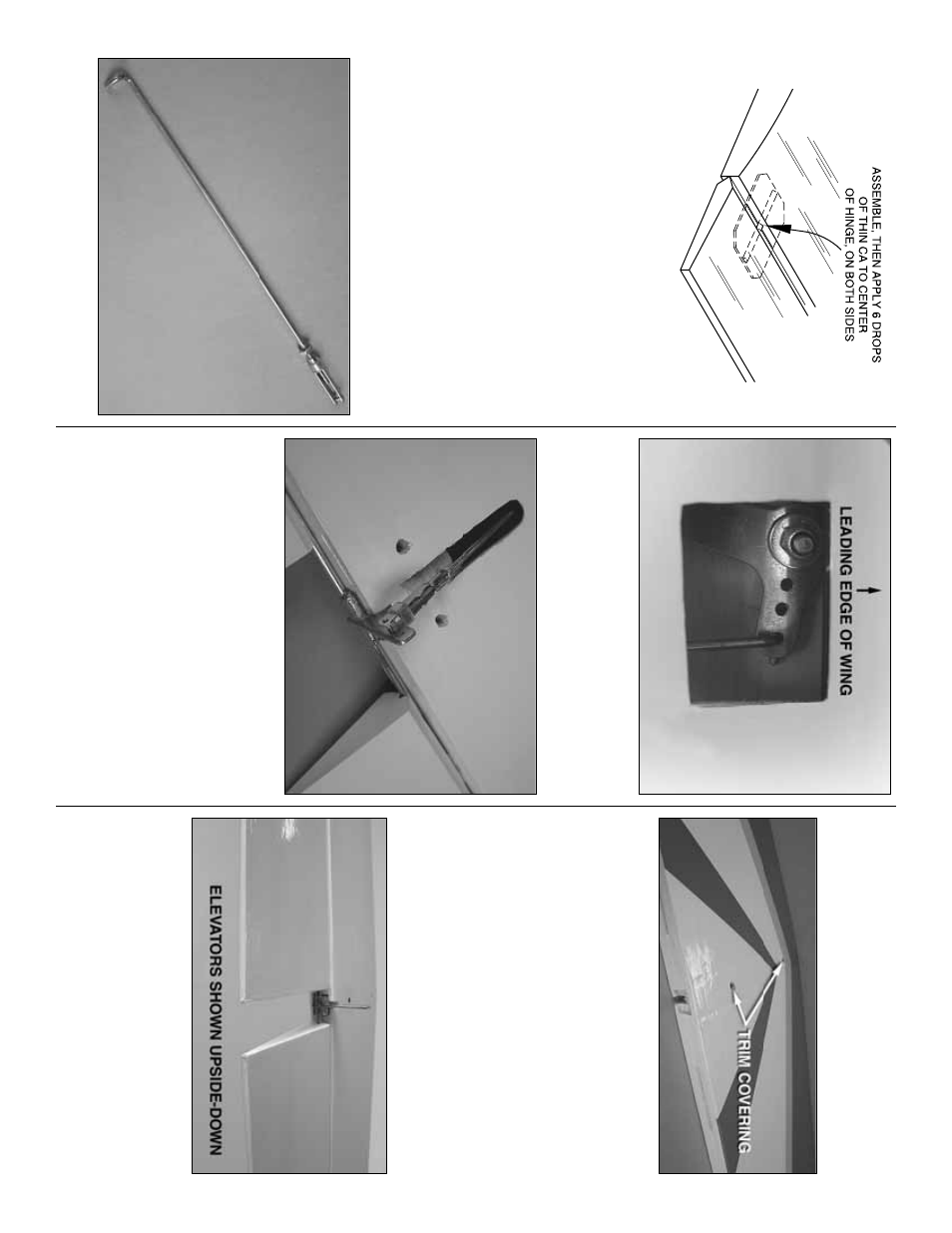
Join the flaps to the wing
b
y
inser
ting the hinges into their mating slots in the
wing.
Apply thin CA to the center of the hinges on
both sides
.
The hinges will secure the flaps in place
while the epo
xy on the joiner wire cures
.
W
ipe a
w
a
y
an
y e
xcess epo
xy with alcohol.
Install Flap Linka
g
e
❏
1.
Thread a 2 mm n
ut, silicone cle
vis retainer
, and
a metal cle
vis onto the flap pushrod wire
.
❏
2.
F
eed the bent end of the pushrod wire through
the cutout in the sheeting near the tr
ailing edge of the
wing.
Connect the pushrod to the outer hole on the
control line bellcr
ank.
❏
3.
With the bellcr
ank in the center position, adjust
the cle
vis until the flaps are neutr
al when the cle
vis is
connected to the middle hole on the flap joiner control
hor
n.
Slide the silicone cle
vis retainer onto the cle
vis
,
add threadloc
king compound to the pushrod threads
,
and tighten the 2 mm n
ut against the cle
vis to secure
it into place
.
ASSEMBLE THE T
AIL
SECTION
Install Ele
v
ator
s
❏
1.
T
rim the co
v
e
ring from the tw
o mounting holes
on the
horizontal stabiliz
er
and the ele
v
ator joiner
wire g
roo
v
e
located in the center of the stab tr
ailing
edge
.
As y
ou did with the wing and flaps
, tr
im the
co
v
e
ring from the pre-cut CA hinge slots both on the
stabiliz
er and the
ele
v
ator
s
.
❏
2.
Locate the holes and slots f
or the
ele
v
ator joiner
wire
at the inside leading edge of both ele
v
a
tors and
tr
im the co
v
e
ring a
w
a
y.
T
empor
ar
ily install CA hinges
halfw
a
y
into each of the pre-cut hinge slots in the
ele
v
ators
.T
est fit the ele
v
ator joiner wire into the joiner
wire holes with the control hor
n pointing do
wn.
❏
3.
T
empor
ar
ily attach the ele
v
ators to the stabiliz
er
b
y
sliding the CA hinges into their matching pre-cut
slots
.V
ie
w the tr
ailing edges of the ele
v
a
tors from the
end of the stab
.
See if the ele
v
a
tors are par
allel with
each other (ha
v
e the same
“up”
and
“do
wn”).
If
necessar
y,
“tw
eak”
the joiner to align them.
Remo
v
e
the joiner wire from the ele
v
ators to do this
.
- 6
-