Top Flite TOPA1020 User Manual
Page 12
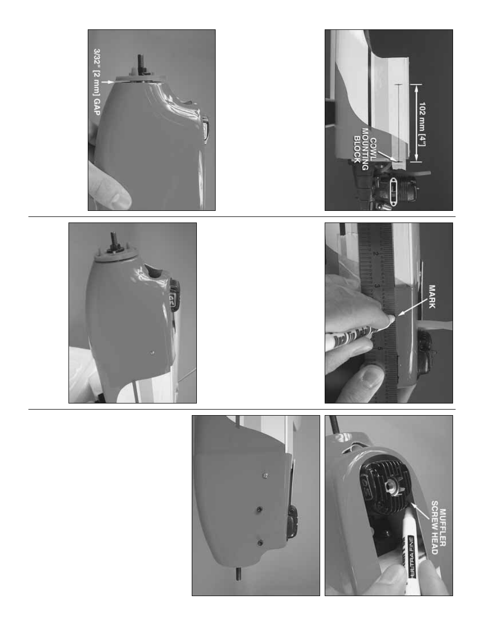
❏
2.
Place a 6" [150 mm] long piece of masking tape
onto the fuselage o
v
er the three mounting b
loc
ks as
sho
wn abo
v
e
.
D
ra
w a line 4" [102 mm] long star
ting
at the center of the co
wl mounting b
loc
ks onto each
piece of tape
.
❏
3.
Place the co
wl on the fuselage and mount the
spinner bac
kplate
.
There should be appro
ximately
3/32" [2 mm] betw
een the spinner and the co
wl.
Align
the co
wl so that the spinner bac
kplate is centered.
When satisfied with its position, use tape to hold the
co
wl in place or ask a helper to hold it steady
.
❏
4.
Using the lines y
ou dre
w on the masking tape
,
measure bac
k 4" [100 mm] from the aft ends of the
lines and tr
ansf
er the mar
ks onto the co
wl.
These
mar
ks will be the scre
w locations f
o
r the co
wl
mounting scre
w
s
.
Dr
ill 1/16" [1.6 mm] holes at the
three mar
ks on the co
wl into the co
wl mounting b
loc
ks
.
❏
5.
Remo
v
e
the co
wl and tak
e off the masking tape
.
Replace the co
wl onto the fuselage and attach the
co
wl with three 2 x 6 mm self-tapping scre
ws and
reinf
orce the holes with thin CA glue
.
❏
6.
Remo
v
e
the co
wl and inser
t the m
u
ffler scre
ws
into the cr
ankcase of the engine
.
Reinstall the co
wl
and position the scre
ws so the
y contact the inside of
the co
wl and mar
k their location.
Remo
v
e
the co
wl
again and cut holes at y
our mar
ks
.
Inser
t the m
uffler
scre
ws through the holes into the engine to confir
m
that the holes are in the correct position.
❏
7.
Remo
v
e
the co
wl one more time
.
Line the
m
u
ffler against the m
u
ffler scre
w holes on the co
wl
and tr
ace its shape
.
Carefully cut out a hole f
or the
m
uffler
.T
rim the hole until y
ou get a good fit.
With the
co
wl still remo
v
ed, attach y
our fuel lines
.
Also
,
consider where y
our needle v
alv
e is positioned.
F
o
r
the engine sho
wn in this man
ual, the remote needle
v
alv
e w
as mounted on its side and an access hole
w
as dr
illed in the co
wl at that location.
- 12
-