Preflight – Top Flite TOPA1020 User Manual
Page 14
- 14
-
❏
1.
Use a f
elt-tip pen or 1/8" [3 mm]-wide tape to
accur
ately mar
k the C
.G.
on the bottom of the wing on
both sides of the fuselage
.
The C
.G.
is located 4-1/8"
[105 mm] bac
k from the leading edge of the wing.
❏
2.
With the wing attached to the fuselage
, all par
ts
of the model installed (ready to fly) and an empty fuel
tank, place the model on a Great Planes CG
Machine
™
, or lift it at the balance point y
ou mar
k
ed.
❏
3.
If the tail drops
, the model is
“tail hea
vy”, and
w
e
ight m
ust be added to the nose to balance
.
If the
nose drops
, the model is
“nose hea
vy”;
w
e
ight m
ust be
added to the tail to balance
.
If additional w
eight is
required, nose w
e
ight ma
y be easily added b
y
using a
“spinner w
e
ight”
(GPMQ4645 f
or the 1 oz [28 g] w
eight,
or GPMQ4646 f
or the 2 oz [57 g] w
e
ight).
If spinner
w
eight is not pr
actical or is not enough, use Great
Planes (GPMQ4485)
“stic
k on”
lead.
A good place to
add stic
k-on nose w
eight is to the fire
w
all (don’t attach
w
eight to the co
wl–it is not intended to suppor
t w
e
ight).
Begin b
y
placing incrementally increasing amounts of
w
eight on the bottom of the fuse o
ver the fire
w
all until
the model balances
.
Once y
ou ha
ve
deter
mined the
amount of w
eight required, it can be per
manently
attached.
If required, tail w
e
ight ma
y be added b
y
secur
ing it to the inside of the hatch doors
.
Note:
Do not rely upon the adhesiv
e on the bac
k of
the lead w
e
ight to per
manently hold it in place
.
O
v
e
r
time
, fuel and e
xhaust residue ma
y soften the
adhesiv
e and cause the w
e
ight to f
a
ll off
.
Use #2
sheet metal scre
ws
, R
TV silicone or epo
xy to
per
manently hold the w
eight in place
.
❏
4.
IMPOR
T
ANT
:
If y
ou f
ound it necessar
y to add
an
y w
eight, rechec
k the C
.G.
after the w
eight has
been installed.
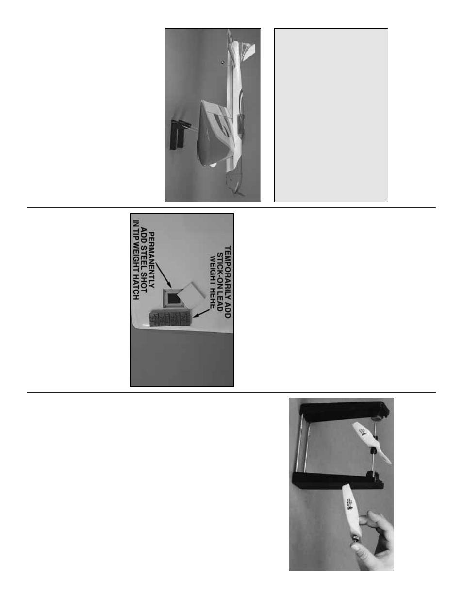
Wing Tip
W
eight
The Score Control Line ARF includes 1-3/4 oz [53 g] of
steel shot.
W
e suggest star
ting out b
y
using 1 oz of
stic
k-on lead w
e
ight applied to the underside of the wing
at the tip near the tip w
e
ight hatch door
.A
dd or subtr
act
w
e
ight after test flying the model to deter
mine the final
amount needed based on flying pref
erence
.
Y
ou can
then per
manently add tip w
e
ight to the model b
y
mixing
the appropr
iate amount of steel shot with epo
xy and
pour
ing it into the tip w
eight compar
tment.
When the
epo
xy has cured, scre
w
the tip w
e
ight hatch door to the
wing using f
our 2 x 6 mm scre
ws or glue it into place
.
PREFLIGHT
Balance Pr
opeller
s
Carefully balance y
our propeller and spare propellers
bef
ore y
ou fly
.
An unbalanced prop can be the single
most significant cause of vibr
ation that can damage
your model.
Not only will engine mounting scre
ws and
bolts loosen, possib
ly with disastrous eff
ect, b
u
t
vibr
ation can also cause y
our fuel to f
oam, which will, in
tur
n, cause y
our engine to r
un hot or quit.
W
e
use a
T
o
p
Flite Precision Magnetic Prop Balancer (T
OPQ5700) in
the w
o
rkshop and k
eep a Great Planes Finger
tip Prop
Balancer (GPMQ5000) in our flight bo
x.
Engine Chec
k
If the engine is ne
w
, f
ollo
w the engine man
uf
acturer’
s
instr
uctions to break-in the engine
.
A
fter break-in,
confir
m that the engine idles reliab
ly
, and maintains
full po
w
er–indefinitely
.
A
fter y
ou r
un the engine on
the model, inspect the model closely to mak
e sure all
scre
ws remained tight, the hinges are secure
, the
prop is secure and all connectors are secure
.
Contr
ol Chec
k
With the lines connected to the leadouts and y
our
assistant holding the model, oper
ate the controls to
mak
e sure the
y
mo
v
e
smoothly
.
If an
y binding or
hesitation is detected, inspect the model and
eliminate the prob
lem.
This is where y
our model should balance f
or the first
flights
.L
ater
, y
ou ma
y wish to e
xper
iment b
y
shifting
the C
.G.
up to 3/8" [9.5 mm] f
orw
ard or 3/8" [9.5 mm]
bac
k to change the flying char
acter
istics
.Mo
ving the
C
.G.
forw
ard ma
y impro
ve the smoothness and
stability
, b
u
t the model ma
y then require more speed
fo
r tak
eoff and mak
e it more difficult to slo
w f
o
r
landing.
Mo
ving the C
.G.
aft mak
es the model more
maneuv
er
ab
le
, b
ut could also cause it to become
too difficult to control.
In an
y case
,
star
t at the
recommended balance point
and do not at an
y
time balance the model outside the specified r
ange
.