Top Flite TOPA0706 User Manual
Page 8
8
folded several times, under the servo and between
each mounting block. After the servo is installed the
spacer will be removed, providing adequate spacing
for vibration isolation.
❏
❏
5. Drill 1/16" [1.6mm] holes through the blocks
for the servo mounting screws. Mount the servo to
the blocks with the screws that came with the servo.
Remove the servo mounting screws and apply a couple
of drops of thin CA in each hole to harden the threads.
Allow the CA to fully harden. Then, reinstall the servos
and remove the spacer.
❏
❏
6. Drill 1/16" [1.6mm] holes through the blocks at
the two hole locations on the top of the hatch. Install
two #2 x 3/8" [9.5mm] fl at head sheet metal screws to
secure the servo mounting blocks to the aileron servo
hatch. Use thin CA to harden the screw threads.
❏
❏
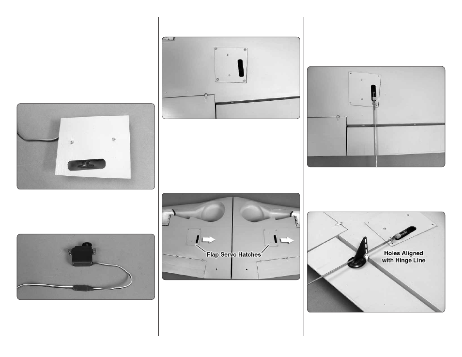
7. Connect a 24" [610mm] servo extension wire
(not included) to the aileron servo. Cut a piece of the
included heat shrink tubing in half and slide it over the
servo connections. Shrink the tubing by applying heat.
❏
❏
8. Use the string in the wing to pull the aileron
wire through the wing.
❏
❏
9. Place the aileron servo hatch with the servo
in the wing. Be certain that the hatch is positioned
correctly as shown. Secure the hatch using four #2 x
3/8" [9.5mm] sheet metal screws and #2 fl at washers.
Use thin CA to harden the screw threads.
❏
10. Go back to step 1 and install the right aileron
servo following the same procedure.
INSTALL THE FLAP SERVOS
❏
❏
1. Install the fl ap servos following the same
procedure used to install the aileron servos. Note that
the fl ap servos face the same direction.
❏
❏
2. Connect a 12" [304mm] servo extension wire
(not included) to the fl ap servo. Secure the extension to
the servo with a piece of heat shrink or electrical tape.
❏
❏
3. Route the fl ap and aileron servo leads to the
root of the wing and out the hole in the top of the wing.
INSTALL THE AILERON & FLAP PUSHRODS
Do the left aileron fi rst. Check that the hinges are
secure by pulling on the ailerons and fl aps.
❏
❏
1. Slide a silicone clevis retainer over a 4-40
threaded metal clevis. Thread a 4-40 nut followed by
the 4-40 metal clevis, threaded 12 turns onto a 4-40
x 12" [304mm] metal pushrod. Attach the clevis to the
aileron servo arm 5/8" [16mm] from the center of the arm.
❏
❏
2. Position the control horn so that it is in line with
the pushrod and over the plywood mounting plate. The
pushrod holes in the control horn should be aligned