Top Flite TOPA0706 User Manual
Page 18
18
❏
3. Insert four 10-32 x 1-1/2" [38mm] socket head cap
screws, #10 lock washers and #10 Fender washers
(not included) through the holes from the backside of
the fi rewall. Slide the plywood engine spacers over the
screws. Apply a drop of threadlocker to the threads of
each screw. Thread the engine standoffs onto the screws
and tighten them against the plywood engine spacers.
❏
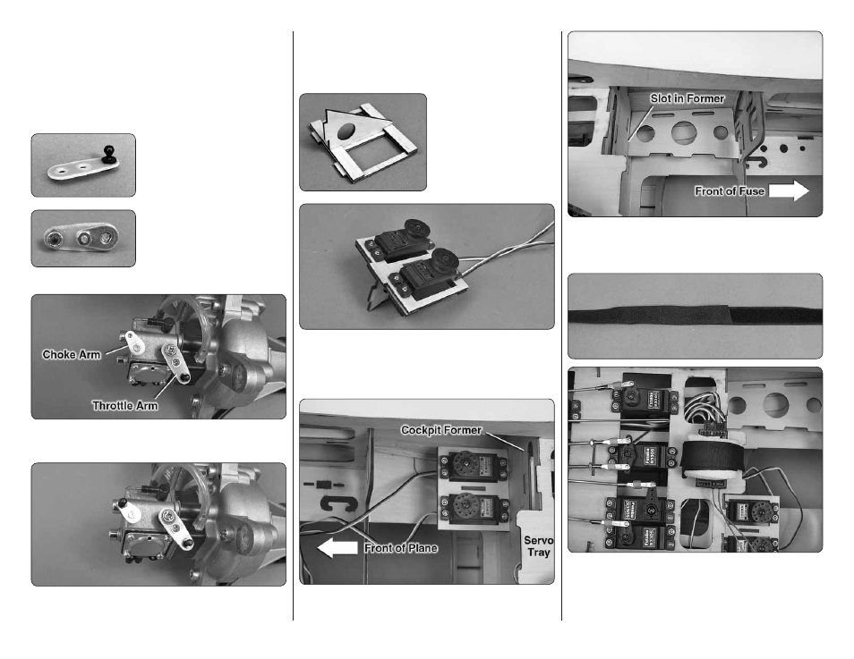
4. If installing the DLE-55
engine, install a 2-56 ball link
ball on the throttle arm
extension and secure it with a
2-56 nylon nut.
❏
5. Remove the throttle arm
from the carburetor. Using the
screw and nut supplied with the
throttle arm extension, attach
the extension to the throttle
arm. Again, use threadlocker on the threads.
❏
6. Reinstall the throttle arm on the carburetor so that
it is opposite the choke arm.
❏
7. Install a 2-56 ball link ball on the choke arm and
secure it with a 2-56 nylon nut.
❏
8. Temporarily install the engine inverted on the
aluminum standoffs. Determine on which side of
the fuselage the throttle and choke servos need to
be installed.
❏
9. Glue the two plywood
servo tray doublers to one
side of the throttle/choke
servo tray. Then, glue the
vertical servo tray support
over the doublers.
❏
10. Install the throttle and choke servos in the servo
tray. Remove the screws and servos and harden the
screw holes with thin CA. Do not reinstall the servos
until the servo tray has been installed in the fuselage.
❏
11. Glue the throttle/choke servo tray to the front of
the cockpit former.
❏
12. On the opposite side of the fuselage, glue the
receiver battery tray to the front of the cockpit former
and the aft fuel tank former.
❏
13. Plug the throttle and choke servos into the receiver.
Wrap the receiver in foam and secure it to the servo tray
with hook and loop material. To make the strap, overlap
by 1" [25mm] the hook material with the loop material.