Get the model ready to fly – Top Flite TOPA0706 User Manual
Page 28
28
GET THE MODEL READY TO FLY
INSTALL THE PROPELLER
❏
1. Carefully balance the propeller and any spare
propellers. An unbalanced propeller can be the single
most signifi cant cause of vibration that can damage
the model. Not only will engine mounting bolts loosen,
possibly with disastrous effect, but vibration may also
damage the receiver and receiver batteries. Vibration
can also cause the fuel to foam, which will, in turn, cause
the engine to run hot and quit.
We use a Top Flite Precision Magnetic Prop Balancer
(TOPQ5700) in the workshop and keep a Great Planes
Fingertip Prop Balancer (GPMQ5000) in our fl ight box.
❏
2. The included aluminum spinner was designed to
be used with the DA-50, DLE-55 and the O.S. GT55
gas engines. Drill the bolt holes through the propeller,
slide the spinner backplate, propeller and prop washer
on the engine prop shaft and install the prop bolts.
❏
3. Install the spinner cone on the engine using an M5 x
85mm socket head cap screw. Use a drop of threadlocker
on the threads. For a more realistic appearance Top
Flite also offers a 3-bladed spinner (TOPA1882) for the
3-blade Zinger prop.
BALANCE THE MODEL LATERALLY
❏
1. With the wing level, have an assistant help you lift
the model by the engine propeller shaft and the bottom
of the fuse under the TE of the fi n. Do this several times.
❏
2. If one wing always drops when you lift the model,
it means that side is heavy. Balance the airplane by
adding weight to the other wing tip. An airplane that
has been laterally balanced will track better in loops
and other maneuvers.
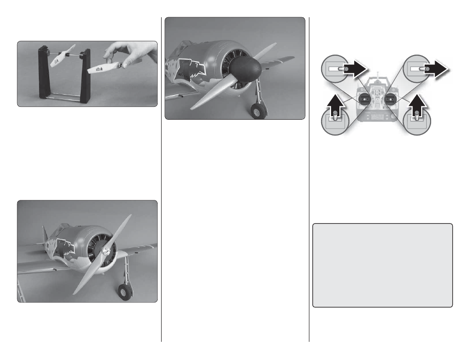
CHECK THE CONTROL DIRECTIONS
❏
1. Switch on the transmitter and receiver and center
the trims. If necessary, remove the servo arms from
the servos and reposition them so they are centered.
Reinstall the screws that hold on the servo arms.
❏
2. With the transmitter and receiver still on, check
all the control surfaces to see if they are centered. If
necessary, adjust the clevises on the pushrods to center
the control surfaces.
FULL
THROTTLE
RUDDER
MOVES
RIGHT
ELEVATOR
MOVES DOWN
RIGHT AILERON
MOVES UP
LEFT AILERON
MOVES DOWN
4-CHANNEL RADIO SETUP
(STANDARD MODE 2)
❏
3. Make certain that the control surfaces and the
carburetor respond in the correct direction as shown in
the diagram. If any of the controls respond in the wrong
direction, use the servo reversing in the transmitter to
reverse the servos connected to those controls. Be
certain the control surfaces have remained centered.
Adjust if necessary.
SET THE CONTROL THROWS
To ensure a successful fi rst fl ight, set up your Giant Fw
190A-3 ARF according to the control throws specifi ed
in this manual. The throws have been determined
through actual fl ight testing and accurate record-
keeping, allowing the model to perform in the manner
in which it was intended. If, after you have become
accustomed to the way the Giant Fw 190A-3 ARF
fl ies, you would like to change the throws to suit your
taste, that is fi ne. However, too much control throw
could make the model too responsive and diffi cult
to control, so remember, “more is not always better.”