Top Flite TOPA0706 User Manual
Page 14
14
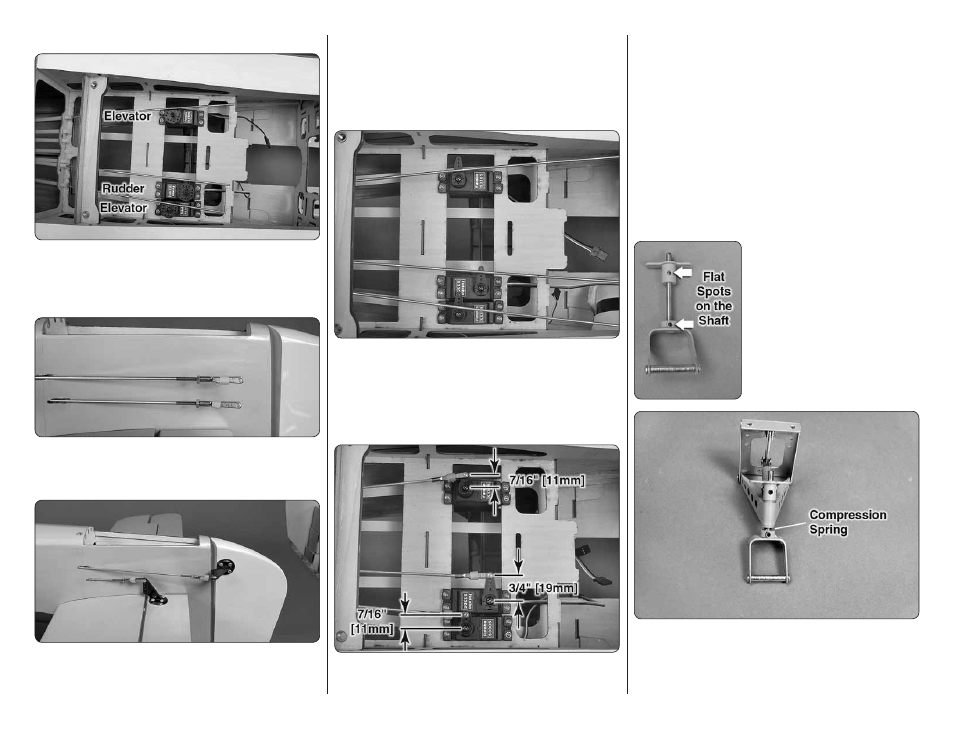
INSTALL THE ELEVATOR & RUDDER SERVOS
❏
1. Insert the three 4-40 x 48" [1220mm] metal
pushrods in the elevator and rudder pushrod outer
pushrod tubes at the aft end of the fuselage. Install two
elevator and one rudder servo in the servo tray as shown.
❏
2. Thread a 4-40 nut, threaded clevis and a silicone
clevis retainer onto both elevator pushrods and the
rudder pushrod.
❏
3. Mount the control horns to the elevators and
the rudder following the same procedure used on the
ailerons, by drilling 3/32" [2.4mm] pilot holes and using
#4 x 1/2" [13mm] sheet metal screws for the rudder
control horn and the front screws in the elevator horns.
IMPORTANT: Use #4 x 3/8" [9.5mm] sheet metal
screws for the aft screws in the elevator control horn.
Don’t forget to harden the holes with thin CA after fi rst
installing, then removing the screws.
❏
4. Connect the receiver battery, rudder and elevator
servos to the receiver. Switch on the transmitter and
center the servos. Install a single arm servo on each
servo, perpendicular to the centerline of the servo.
To obtain the required amount of rudder throw, a 3/4"
[19 mm] servo arm was installed on the rudder servo.
❏
5. Install solder clevises on the elevator servo arms in
the hole 7/16" [11mm] from the center of the servo arm.
Install a solder clevis on the rudder servo arm in the hole
3/4" [19mm] from the center of the servo arm. Follow
the same procedure that was used for the aileron and
fl ap pushrods. Mark the elevator and rudder pushrods
where they are to be cut for the solder clevises. One at a
time, remove the threaded metal clevis from the control
horn end, remove the pushrod from the fuselage, cut it
to the correct length and solder a metal solder clevis on
the end. Reinstall the pushrod inside the fuselage and
connect the solder clevis to the servo arms. Reinstall
the threaded metal clevis and 4-40 nut. Don’t forget
to use a silicone clevis retainer on all the clevises.
MOUNT THE RETRACTABLE TAIL GEAR
❏
1. Remove the steering arm
from the Robart #160 retractable
tail gear assembly (not included).
File a fl at spot near the top of
the shaft for the set screw in the
steering arm to lock onto. File a
second fl at spot near the bottom
of the shaft for the set screw in
the strut. Mount the strut on the
shaft with a drop of threadlocker
on the set screw.
❏
2. Install the compression spring, included with the
Fw 190, on the shaft, between the strut and the tail
gear frame. Compress the spring while tightening the
set screw in the steering arm.