Connections when using with the vm-3000 system, Vp-2241, Cable: awg 6 – awg 0 (1/0) – Toa VX-200PS SA User Manual
Page 22
22
Lead-acid Battery
DC power
output terminals
(–)
(–)
(–)(–)(+)(+)
(–)(–)(+)(+)
(+)
(–)
(+)
DC power
input terminals
VP-2241
PA LINK
VP-200VX
28 V
4.8 A
DC POWER IN
PA OUT (SP LINE)
C
H
VP-2241
PA LINK
VP-200VX
28 V
4.8 A
DC POWER IN
PA OUT (SP LINE)
C
H
VM-3240E/3360E
24V
MAX150A
BATTERY POWER IN
( )
( )
( )
230V
50/60Hz 240W
6
1
5
4
3
2
6
1
5
4
3
2
DC POWER OUT (+) MAX 25A (DC 20V-40V)
PS IN (
+
) MAX 25A (DC20V-40V)
DS – SF
FUSE
LINK
DETECT(VX-200PS)
OFF
ON
ON OFF
THERMISTOR
PS3
PS2
1,2:PS1
PS IN
5,6:PS3
3,4:PS2
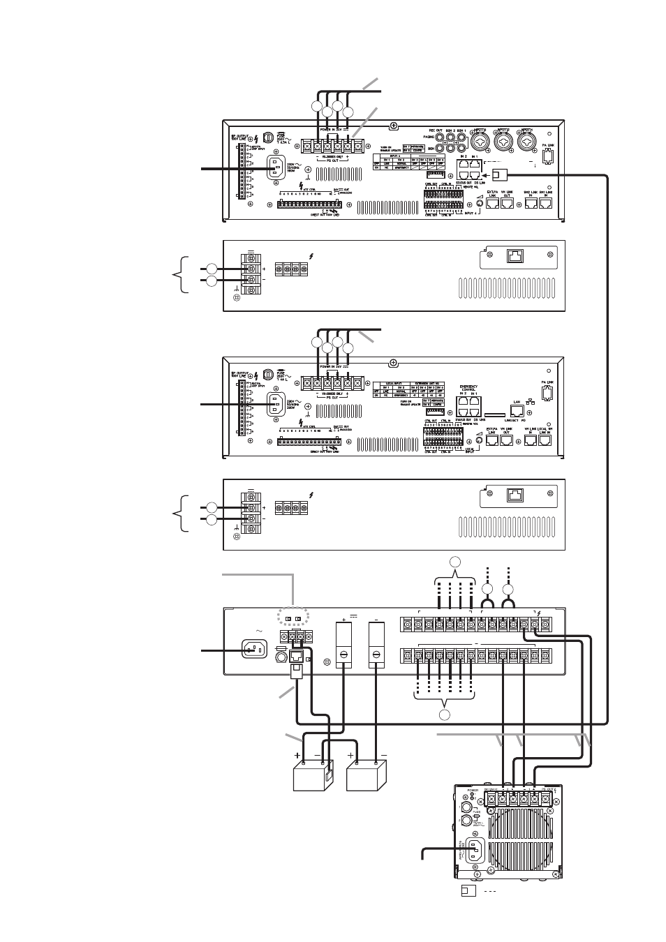
Note
Make PS2 and PS3 switch settings according to the total number of
connected power supply units VX-200PS and VM-3240VA/3360VA
(power supply unit incorporated); set PS2 to ON for 2 units, and PS2
and PS3 to ON for 3 units.
Note that these power supply units should be connected to the PS IN
(+) terminals 1 and 2 for the 1st unit, 3 and 4 for the 2nd unit, and 5
and 6 for the 3rd unit.
See “Note” below.
RJ45 male connector
VX-2000DS
VX-200PS
Cat. 5 STP
Caution
The charging current from the
VX-2000DS is 5 A maximum.
Applicable Batteries:
Panasonic LC-X1265PG/APG
Cable:
AWG 6 – AWG 0 (1/0)
d
c
a
a
b
d
c
d
c
c
VM-3240VA/3360VA
From VX-2000DS
From VX-2000DS
From VX-2000DS
From VX-2000DS
d
d
b
c
d
d
Note
Remove the short bar attached at the factory.
230 V AC
220 V AC
50/60 Hz
230 V AC
220 V AC
50/60 Hz
230 V AC
220 V AC
50/60 Hz
230 V AC
220 V AC
50/60 Hz
Cable: AWG 10 – AWG 8
Cable: AWG 10 – AWG 8
Cable:
AWG 14 – AWG 10
(line resistance within
10 mΩ/pair)
6. CONNECTIONS WHEN USING WITH THE VM-3000 SYSTEM