Ds link terminal connections, Link ds – sf link ds – sf – Toa VX-200PS SA User Manual
Page 21
21
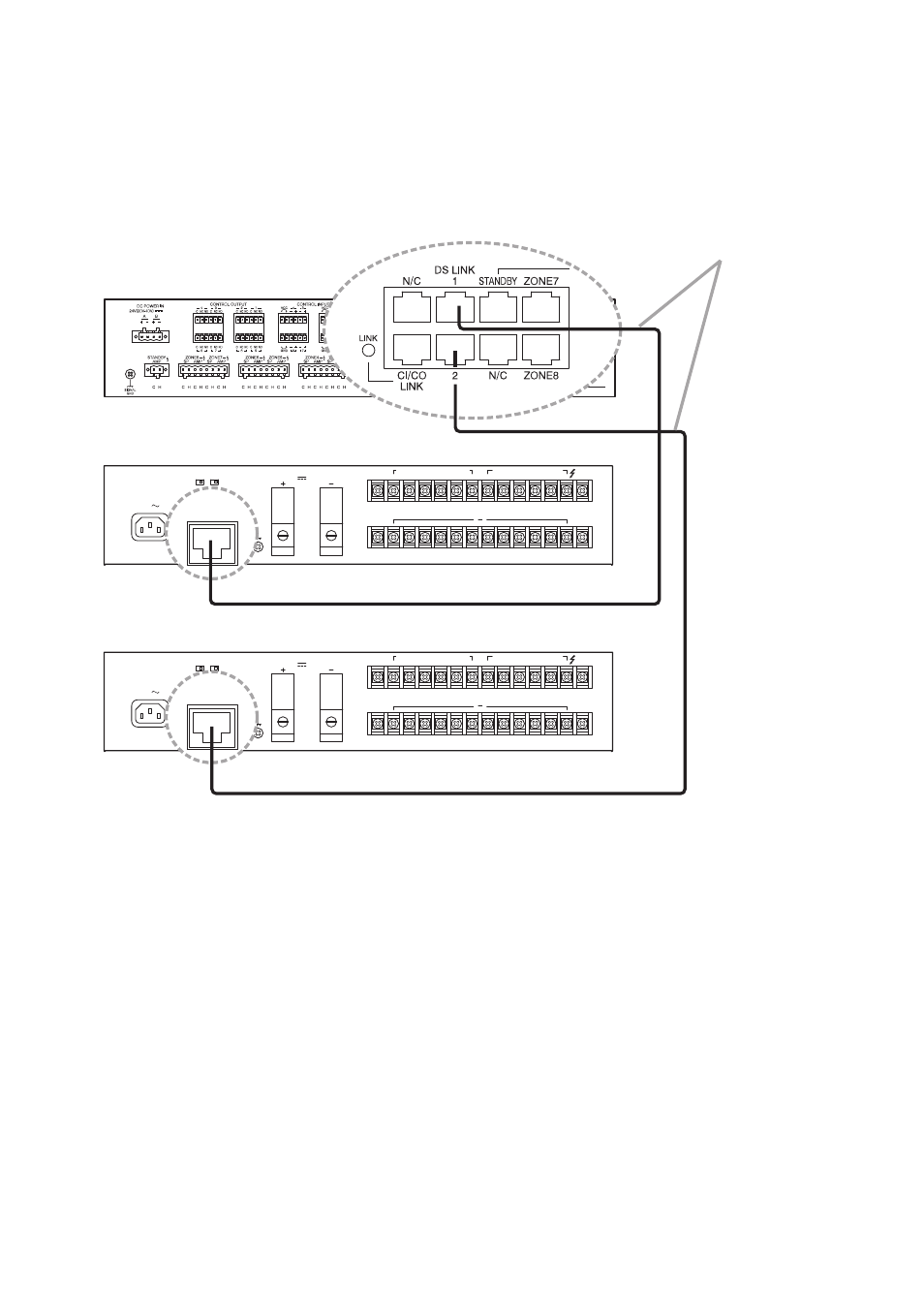
5.3. DS Link Terminal Connections
Connect the DS-SF LINK terminal of the VX-2000DS to the DS Link terminal of the SX-2000SM or SX-
2100AO. The figure below shows a connection example when the VX-2000DS units are connected to the SX-
2100AO. This connection also applies to the SX-2000SM.
T3.15A L
24V
MAX150A
BATTERY POWER IN
( )
( )
( )
DS – SF
FUSE
LINK
SETTING
DC
AC
6
1
5
4
3
2
6
1
5
4
3
2
230V
DC POWER OUT (
+
) MAX 25A (DC 20V-40V)
PS IN (
+
) MAX 25A (DC20V-40V)
50/60Hz 240W
DS – SF
DETECT(VX-200PS)
OFF
ON
ON OFF
THERMISTOR
PS3
PS2
1,2:PS1
PS IN
5,6:PS3
3,4:PS2
T3.15A L
24V
MAX150A
BATTERY POWER IN
( )
( )
( )
DS – SF
FUSE
LINK
SETTING
DC
AC
6
1
5
4
3
2
6
1
5
4
3
2
230V
DC POWER OUT (
+
) MAX 25A (DC 20V-40V)
PS IN (
+
) MAX 25A (DC20V-40V)
50/60Hz 240W
DS – SF
DETECT(VX-200PS)
OFF
ON
ON OFF
THERMISTOR
PS3
PS2
1,2:PS1
PS IN
5,6:PS3
3,4:PS2
SX-2100AO
VX-2000DS (No. 1)
VX-2000DS (No. 2)
LINK
DS – SF
LINK
DS – SF
Applicable cable: Cat. 5 STP
(Category 5 shielded twisted pair cable)
DS Link Terminals
Control connector
Control connector