Tightening torque: 6 – 8 nm – Toa VX-200PS SA User Manual
Page 13
13
Cable cross
sectional area
16 mm
2
25 mm
2
35 mm
2
50 mm
2
180 cm
280 cm
400 cm
570 cm
AWG 6
AWG 4
AWG 2
AWG 0 (1/0)
80 cm each
130 cm each
190 cm each
275 cm each
20 cm
20 cm
20 cm
20 cm
Length (2 mΩ)
AWG
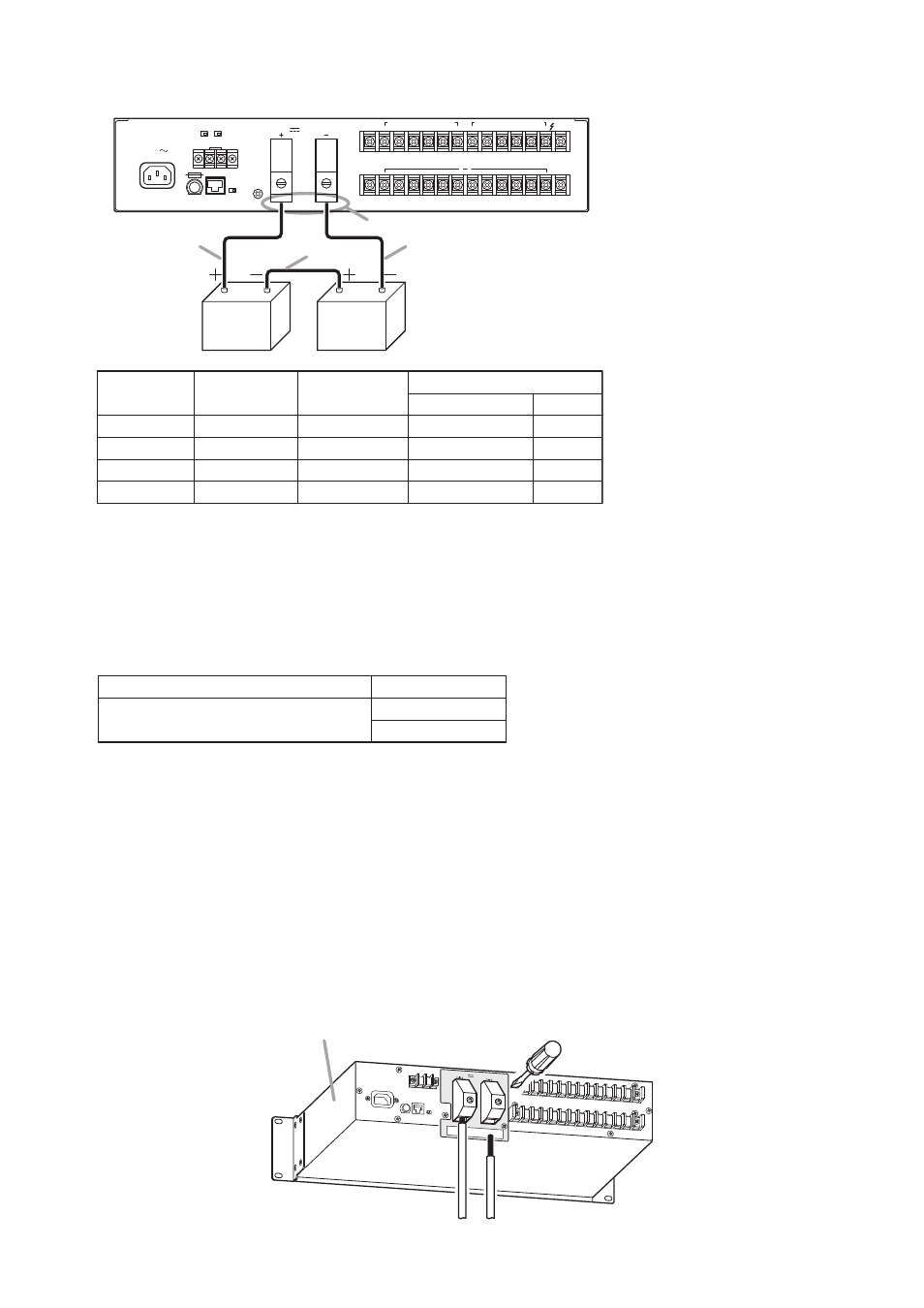
Example of wire length
Cable A, Cable C
Cable B
VX-2000DS’ Battery connection terminals
Battery terminals
6 – 8 Nm
4.1 – 5.6 Nm (M6)
8.2 – 5.6 Nm (M8)
• Use the battery connection cables as short in length and as large in diameter as possible.
24V
MAX150A
BATTERY POWER IN
( )
( )
( )
230V
50/60Hz 240W
6
1
5
4
3
2
6
1
5
4
3
2
DC POWER OUT (+) MAX 25A (DC 20V-40V)
PS IN (
+
) MAX 25A (DC20V-40V)
DS – SF
FUSE
LINK
DETECT(VX-200PS)
OFF
ON
ON OFF
THERMISTOR
PS3
PS2
1,2:PS1
PS IN
5,6:PS3
3,4:PS2
Battery
Cable A
Cable C
Cable B
Battery
VX-2000DS
Battery connnection terminals
• Total resistance of the battery connection path should be less than 4 mΩ, which includes resistance of all of
wire, terminal, fuse, and terminal points.
For reference, refer to each resistance as follows.
Resistance of terminal, fuse (if provided): 1 – 2 mΩ
Resistance of terminal point:
0.1 – 0.5 mΩ
• Fasten the bolts, nuts, and screws of the unit's battery connection terminals and battery terminals with the
torque as shown below.
Step 1. Allow more than 10 seconds to elapse after removing the power cord from the VX-2000DS' rear-
mounted AC inlet.
Step 2. Insert the positive battery cable into the VX-2000DS' rear-mounted BATTERY POWER IN positive
terminal from the bottom side of the connector, then tighten the terminal screw with a flat screwdriver.
Note
Never connect the negative cable first to avoid battery short-circuit that occurs if the positive cable
should contact the unit chassis or equipment rack.
Step 3. Connect the negative battery cable to the negative terminal in the same manner as Step 2.
1
2
VX-2000DS
24V
MAX150A
BATTERY POWER IN
Tightening torque: 6 – 8 Nm