Caution – Toa DP-K1 User Manual
Page 7
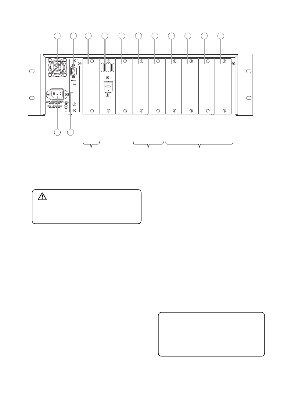
6. Cooling Fan
7. RS-232C Communication Port
The port is solely for the maintenance use.
8. Remote Control Module Slot
The remote control module's dedicated slot.
9. Network connection terminal panel
The blank panel is attached to the unit as shipped
by the factory.
You can remove the network connection terminal
from the front panel, and attach it to this panel.
For repositioning the terminal from the front panel,
refer to p. 15.
10. Empty slot
Unused slot
11. Output module slot
Slot for output channels 5 – 8.
12. Output module slot
Slot for output channels 1 – 4.
13. Input module slot
Slot for input channels 7 and 8.
14. Input module slot
Slot for input channels 5 and 6.
15. Input module slot
Slot for input channels 3 and 4.
16. Input module slot
Slot for input channels 1 and 2.
17. AC inlet
Connect this inlet to the wall AC outlet using the
supplied power cord.
18. MAC address
A 12-digit hexadecimal network address peculiar
to the unit.
7
00-40-9D-26-14-58
6
7
8
9
10
11
12
13
14
15
16
17
Input module slot
Output module slot
Remote control module slot
Slot number
Module type
Input & output
channel
1
2
3
4
5
6
7
8
9
Inputs
7 & 8
Inputs
5 & 6
Inputs
3 & 4
Inputs
1 & 2
Outputs
5 – 8
Outputs
1 – 4
18
[Rear]
CAUTION
Do not block the fan exhaust vent. Doing so
may cause heat to build up inside the unit and
result in fire.
The MAC address is used to make the unit's
network setting.
Record it for later reference.
For network setting procedures, refer to the
software setting instruction manual included
in the supplied CD.