Pc connections, Connections – Toa DP-K1 User Manual
Page 14
14
Lighting
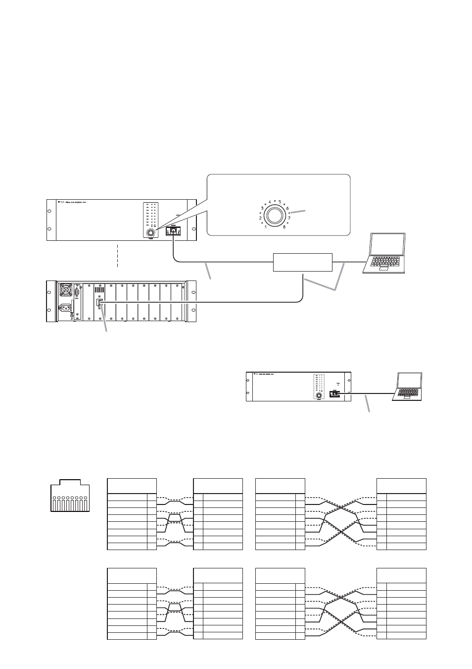
Connection from the rear-mounted terminal
Network connection terminal*
2
PC with the dedicated
software installed
Straight through cable*
1
Straight through cable*
1
Network connection terminal
Switching hub
Connection from the front-mounted terminal
UTP Category 5 cable fitted with RJ45 connectors
Example when the terminal mounting position is changed to
the rear from front. (For repositioning the network connection
terminal, refer to the next page.)
*
1
*
2
The dot LEDs around the preset knob
remain lit while the unit is communicating
with the PC.
DP-K1
Cross cable*
1
8. PC CONNECTIONS
8.1. Connections
Connect the PC to the unit's network connection terminal via a switching hub.
Use a straight through cable for connection.
Notes
• To enable communications between the PC and the unit, set the unit's network setting needs to be set on the
PC. For communication settings, refer to the software setting instruction manual included in the supplied CD.
• The PC can communicate with only one unit at a time.
[Memo]
We have confirmed that the PC having the specifications below can communicate with up to 30 units at a time.
Processor: Intel® Pentium® M Processor/1.6 GHz
Memory:
512 MB RAM
Tip
You may connect the DP-K1 to the PC directly by
using a cross cable.
Depending on the PC settings, however, this direct
connection may not be allowed. In such cases, make
connections via a switching hub as shown above.
[Reference: LAN cable wiring diagrams]
The LAN wiring standard of ANSI/TIA/EIA-568-B specifies 2 wiring standards T568A and T568B for straight
through cable wirings.
8
7
6
5
4
3
2
1
1
2
3
4
5
6
7
8
• RJ45 pin No.
RJ45 pin No.
and color
1
2
3
4
5
6
7
8
White/Green
Green
White/Orange
Blue
White/Blue
Orange
White/Brown
Brown
RJ45 pin No.
and color
1
2
3
4
5
6
7
8
White/Orange
Orange
White/Green
Blue
White/Blue
Green
White/Brown
Brown
RJ45 pin No.
and color
1
2
3
4
5
6
7
8
White/Green
Green
White/Orange
Blue
White/Blue
Orange
White/Brown
Brown
RJ45 pin No.
and color
1
2
3
4
5
6
7
8
White/Orange
Orange
White/Green
Blue
White/Blue
Green
White/Brown
Brown
• T568A Straight through cable wiring
• T568B Straight through cable wiring
• Cross cable wiring (T568A base)
• Cross cable wiring (T568B base)
RJ45 pin No.
and color
White/Green
Green
White/Orange
Blue
White/Blue
Orange
White/Brown
Brown
1
2
3
4
5
6
7
8
RJ45 pin No.
and color
White/Orange
Orange
White/Green
Blue
White/Blue
Green
White/Brown
Brown
1
2
3
4
5
6
7
8
RJ45 pin No.
and color
White/Orange
Orange
White/Green
White/Brown
Brown
Green
Blue
White/Blue
1
2
3
4
5
6
7
8
RJ45 pin No.
and color
White/Green
Green
White/Orange
White/Brown
Brown
Orange
Blue
White/Blue
1
2
3
4
5
6
7
8