Warning – Toa DP-K1 User Manual
Page 15
15
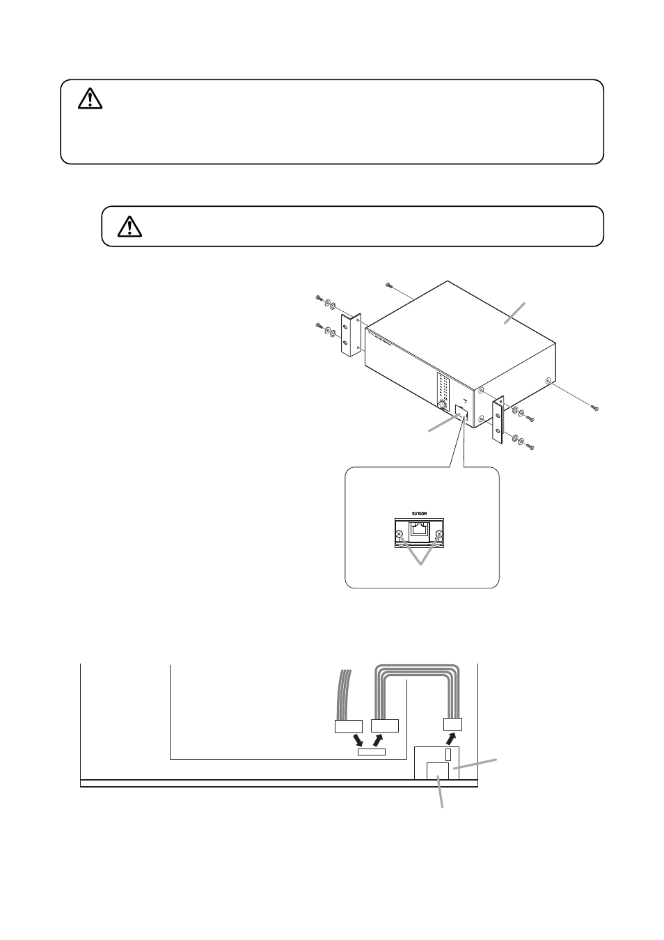
[Inside of the pocket cover]
Screws
Network connection terminal
DP-K1
2
6
Case
Pocket cover
CN701
CN1
Front panel side
Interior with the case removed
Main PC board
4
3
Ethernet PC board
Network connection terminal
8.2. Repositioning the Network Connection Terminal
Step 1. Plug out the power cord from the AC wall outlet.
Step 2. Remove 6 screws and washers on
both sides of the unit to detach the
case.
Step 3. Detach a harness connected to the
Ethernet PC board and Main PC
board.
Note
The removed harness is not used.
Step 4. Connect a 9P connector taped to the
Main PCB to the CN701 connector
after taking it off.
Step 5. Detach the pocket cover from the
front panel.
Step 6. Remove 2 screws to detach the
Ethernet PC board from the front
chassis.
Note
The removed screws are used in
Step 11.
Step 7. Reattach the removed packet cover.
These servicing instructions are for use by qualified personnel only. To avoid electric shock, do not
perform any servicing other than that contained in the operating instructions unless you are qualified to
do so. Refer all servicing to qualified service personnel.
WARNING
Never do this work with the power cord connected to the outlet,
as doing so may cause electric shock.
WARNING