Toa DP-K1 User Manual
Page 16
16
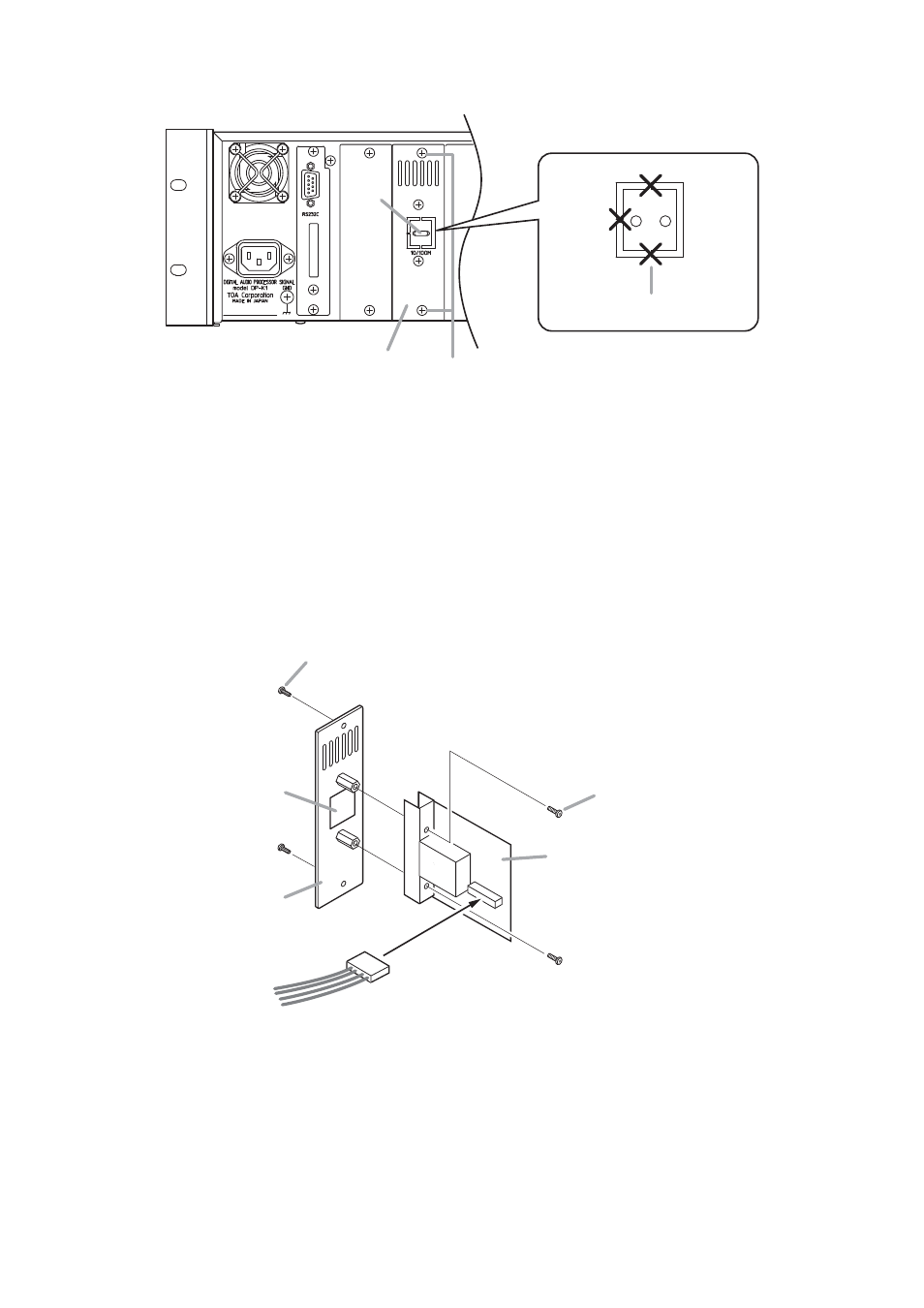
Network connection
terminal panel
DP-K1 rear
8
9
Cut at 3 places with nippers.
10
CN1
11
Ethernet PC board removed in Step 6
Backside of panel
Knockout hole
Harness removed in Step 10
Screw removed in Step 6
Screw removed in Step 9
12
13
Step 8. Cut the cable tie on the center of the rear-mounted network connection terminal panel.
Step 9. Remove 2 screws to detach the network connection terminal panel.
Note
The removed screws are used in Step 13.
Step 10. Detach the harness from the backside of the panel, then cut the knockout hole on the center of the
panel using nippers.
Step 11. Mount the Ethernet PC board to the backside of the network connection terminal panel.
Use 2 screws removed in Step 6.
Step 12. Connect the 5P connector of the harness removed in Step 10 to the CN1 on the Ethernet PC board.
Step 13. Reattach the removed network connection terminal panel.
Step 14. Replace the removed case and rack mounting brackets.
- D-2000 Series Installation (84 pages)
- DD-2000 Series Manual (24 pages)
- D-2000 Series Read Me First (12 pages)
- D-2012AS (2 pages)
- D-2012C (4 pages)
- D-901 (96 pages)
- CR-273 (20 pages)
- CR-413-6 (20 pages)
- EV-20R (20 pages)
- MP-1216 (8 pages)
- MB-WT3 (2 pages)
- MT-251H (1 page)
- F-2322C (12 pages)
- F-2852C (12 pages)
- SC-630 (2 pages)
- ES-0851 (4 pages)
- ES-C0651 (4 pages)
- F-1000B (18 pages)
- F-122C (12 pages)
- F-122CU (20 pages)
- F-122CU2 (16 pages)
- F-1300B (18 pages)
- F-1522SC (8 pages)
- AN-9001 (1 page)
- C-AL80 (16 pages)
- DP-K1 (102 pages)
- DP-L2 v.2.00 (28 pages)
- DP-SP3 Protocol (14 pages)
- DP-SP3 (24 pages)
- DP-SP3 (75 pages)
- E-232 (8 pages)
- AT-063AP (4 pages)
- BS-1015BSB (8 pages)
- BS-1030B (4 pages)
- BS-634 (4 pages)
- BS-1034EN (8 pages)
- BS-1110W (4 pages)
- BS-301B (8 pages)
- BS-301B AS (4 pages)
- MB-WT1 (1 page)
- S-D7300 (16 pages)
- VX-200SP-2 (24 pages)
- YA-1000A (1 page)
- ZM-9001 (2 pages)