Testing, Reset button opening – Tii SVM-1R-P User Manual
Page 2
Testing
Note: Hardware reset is needed to switch device to its
initial state. The initial state for the SVM-1R-P is Telco
mode.
1.
For initial test connect Local Phone and MTA only. Check
for dial tone, if tone is present then the device isn’t reset.
Proceed to next step. If tone isn’t present skip step 2.
2.
Gently push the reset button once with a blunt object to
ensure the service to the customer is from the Telco
Service Provider, observe the green LED blinking.
3.
The SVM-1R-P will automatically switch to VoIP line and
stay in this mode until reset again.
CAUTION:
TO AVOID PERMANENT DAMAGE TO RESET
BUTTON DO NOT USE EXCESSIVE FORCE OR A
POINTED OBJECT TO ACTIVATE THE RESET
BUTTON.
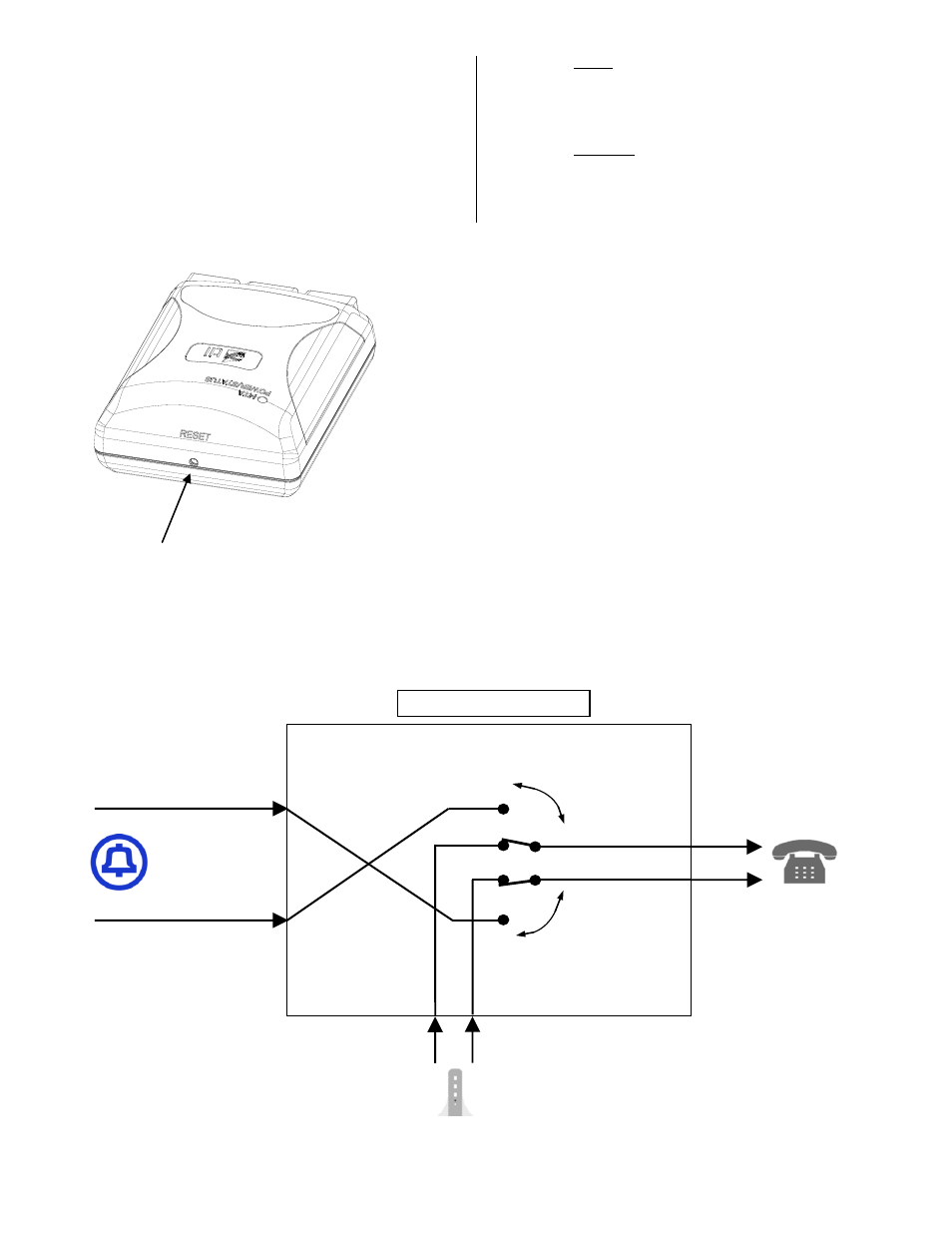
Figure 3
Reset Button
Opening
VoIP from MTA (Pin 3)
Telco Input (Pin 2)
Telco Input (Pin 3)
TELCO
VoIP from MTA (Pin 2)
TELCO
MTA
MTA
TELCO
DIGITAL
MODEM
LOCAL
PHONE
Local Phone (Pin 2)
Local Phone (Pin 3)
SVM-1R-P
FUNCTIONAL DIAGRAM
Figure 4
- OF025PFNOPNST1 (2 pages)
- IF025PFNOPNST1 (2 pages)
- 210 (2 pages)
- 220 (1 page)
- 231-2 (1 page)
- 68T-2S-4 (1 page)
- 68M-2-1T (1 page)
- 68M-12-1T (1 page)
- 68M-1-1T (1 page)
- 170-06-03 (2 pages)
- 69T (1 page)
- ISB (2 pages)
- ISB-MB (1 page)
- 372S-12LP (1 page)
- 372S-12 (1 page)
- 80-100 (1 page)
- 80-400 (1 page)
- 80-410V-45 (1 page)
- SCT-A (1 page)
- 87 (1 page)
- 95S Series (2 pages)
- 95S Series (3 pages)
- 96-00-1 SERIES (2 pages)
- 96-00-4 SERIES (2 pages)
- 97 (2 pages)
- 97C (1 page)
- 99S SERIES (2 pages)
- 831E (1 page)
- 831W2 (1 page)
- 856E (1 page)
- VIS-4 (2 pages)
- ONT-SS (1 page)
- VIS-2 (2 pages)
- FDT1 Series (2 pages)
- FDT2 Series (2 pages)
- FDH1 (14 pages)
- 169F SERIES (2 pages)
- 506F (2 pages)
- 506F-03 (2 pages)
- 506F-02-01-04 (2 pages)
- 506F-01-01-01/-02/-03 (2 pages)
- UVS-12 (1 page)
- 761-4T-12 (2 pages)
- VIS-3 (2 pages)
- FET1 Series (2 pages)