Tii ISB PLATE User Manual
Tii Equipment
P/N 92233801 • Rev B• 10/30/2009
Warranty: If this unit fails during the warranty period, contact tii customer service to authorize return. Unit may be returned prepaid.
Model ISB
Intercom System Bypass
Model ISB PLATE
12 Position Panel
Installation Note
Description
1. This Installation Note covers the description
and installation of the TII ISB and ISB PLATE.
The TII ISB is deployed in conjunction with the
TII ISB PLATE panel. The TII ISB is supplied
as an individual module. The ISB PLATE can
accommodate up to 12 TII ISB modules. The
TII ISB has been designed to provide DSL
signal bypass in MDU applications where
POTS lines with DSL signals are required to
interface with intercom systems. The TII ISB
should only be used for indoor applications.
IDC rockers are used to terminate 26-22 AWG
solid wire. Test points are provided to test
signal integrity at input and output IDC’s.
Features
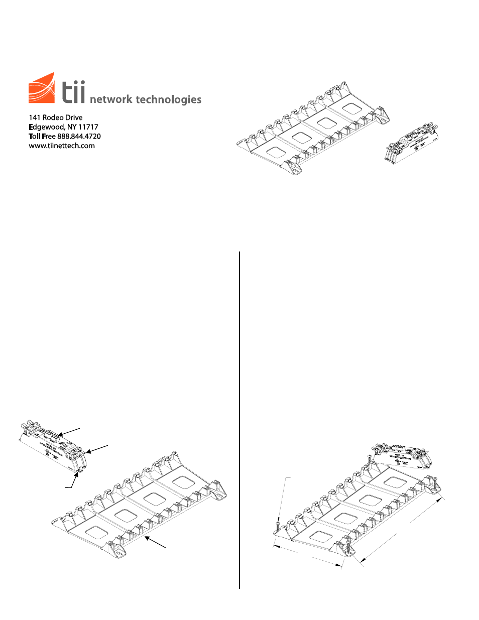
Installation
1. Locate a suitable flat, dry area to install the
ISB PLATE panel.
NOTE: The ISB modules and the ISB plate must be
located in an restricted Telco personnel access
only area of the building.
2. Mount the ISB PLATE panel with (4) #8 Sheet
Metal Screws (Hardware Not Supplied). Refer
to Figure 1 for ISB PLATE mounting
dimensions. If the ISB PLATE panel is already
installed, identify the position in which the TII
ISB module is to be installed.
3. Holding the module on an angle as shown in
Figure 1, engage the left side fingers under
the catch on the ISB PLATE panel. Slowly
lower the module and align the latch with the
panel and engage module to the panel.
Confirm that the module is securely engaged
to the panel.
Figure 1
11.75
6.50
(4) #8 SCREWS
ISB PLATE
ISB
CAN ACCOMMODATE UP
TO 12 ISB MODULES
IDC ROCKERS
TEST
PORTS
WIRE
GUIDES