Tii 79 Series User Manual
Page 2
TII P/N 92225101
Telco Service
4.2 Wire spaded lugs to the corresponding Telco
Service Input.
4.3 Insert the RJ-11 interface plug into the 3 pair
Telco input receptacle.
4.4 Insert wires into customer wire guides at the
same time until they bottom out. While holding
wires in wire guides, terminate rocker with thumb
(lower rocker all the way).
4.5 Terminate additional wire pairs to the remaining
rockers as required.
VoIP Service
4.6 Connect the Digital Voice Service Input wires to
the Blue MTA rocker, following step 4.4.
4.7 Insert the RJ-11 interface plug into the MTA input
receptacle.
4.8
Insert wires into the customer wire telco output
rockers as required.
5. TESTING
5.1 Test for line continuity using the test points. (Figure
1).
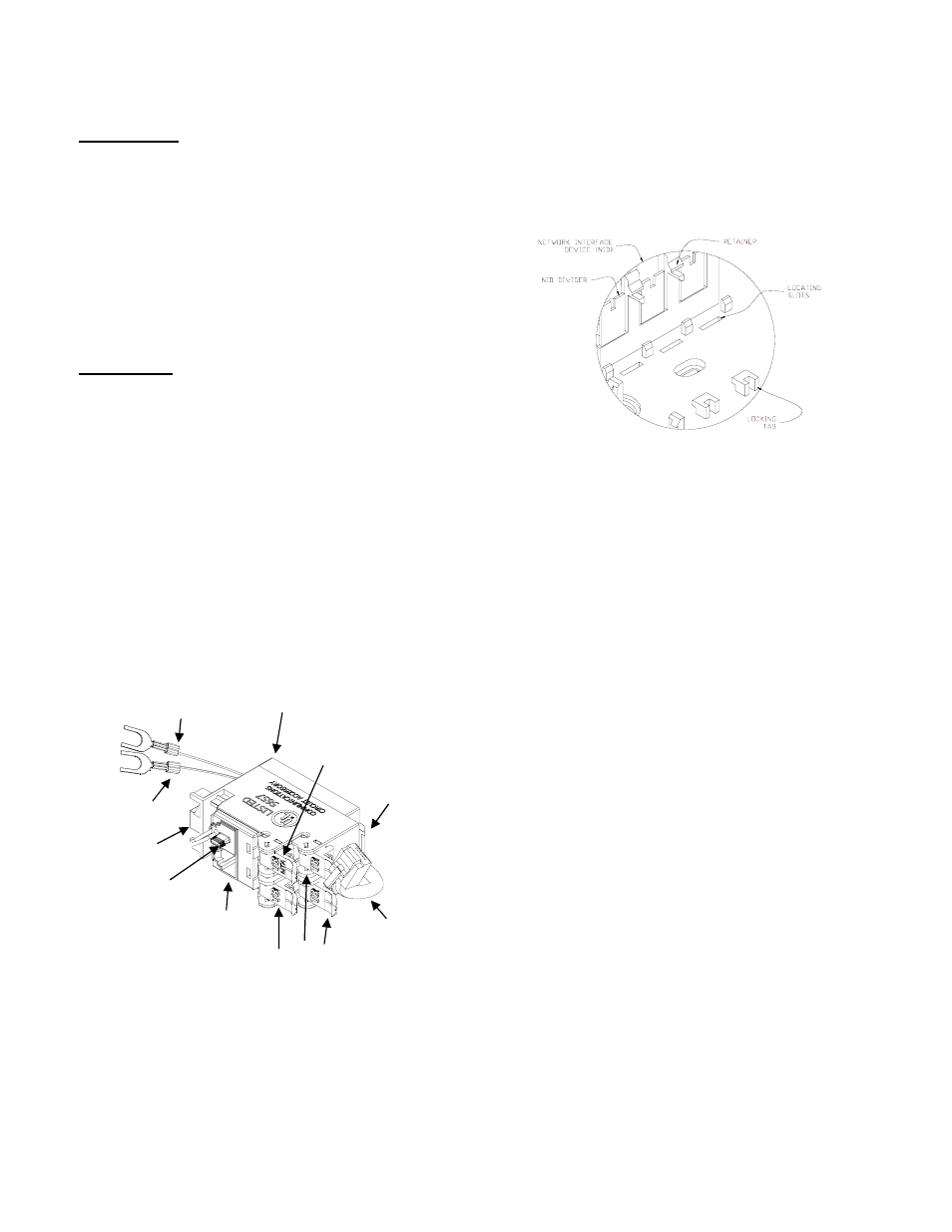
FIGURE 2
Locking Hinge
Test Points
Customer Wire Telco
Output Terminations
Digital Voice
Service Input
RJ-11 Interface
Tip (Green)
Ring (Red)
3 Pair Telco Input
MTA Input
Locating Fingers
TII 79 Wiring
FIGURE 3
TII 79 Installation