Tii ADX-SERIES User Manual
Page 2
Wiring
1. The two upper ports of the Angle Driver are
intended to terminate subscriber (customer)
wires. Telco drop (feeder) wires must be
terminated in the two lower ports of the Angle
Driver.
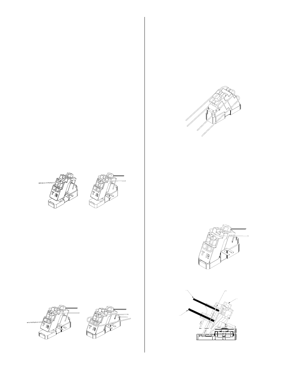
2. Upper Port Subscriber Connections (See
Figure 3) Subscriber terminations are already
made at the factory. If it is necessary to re-
terminate a subscriber wire, do so as follows:
3. Do not strip wire insulation. Make certain wire
ends are cut flush with insulation.
4. Unscrew Angle Driver screw to the full upright
position.
5. Fully insert the two subscriber wires into their
respective tip and ring (color-coded) ports.
6. Insert while holding the two subscriber
connection wires in place. Ensure wires are
fully inserted beyond the IDC connector
(See Figure 7). Tighten Drive Screw to the full
down position. Pull on wires to ensure
proper connection. Wires should remain
securely in place.
7. Dress the wires through the strain relief slots
to hold them in place (See Figure 3).
Figure 3
Lower Port Telco Connections
(See Figure 4)
1. Do not strip wire insulation. Make certain wire
ends are cut flush with insulation.
2. Unscrew Angle Driver screw to full upright
position.
3. Fully insert the two feeder (telco) wires into
their respective tip and ring (color-coded)
ports. Ensure wires are fully inserted
beyond the IDC connector (See Figure 7).
4. While holding the two telco wires in place,
tighten Drive Screw to full down position. Pull
on wires to ensure proper connection.
Wires should remain securely in place.
Figure 4
Testing
1. Feeder and subscriber wires must be
segregated between the upper and lower ports
to facilitate isolation testing (See Figure 5).
Upper and Lower Port Connected
1. With Driver in the fully closed position, insert
test clips into tip/ring test port access holes
located at top of driver. Perform customary
tests.
Figure 5
Testing Subscriber Connections
(See Figure 6)
1. Loosen drive screw so driver is in the full
upright position.
2. Remove telco wires from lower ports of driver.
3. Tighten drive screw so driver is in the full
down position.
4. With Driver in the fully closed position, insert
test clips into tip/ring test port access holes
located at top of driver. Perform customary
tests.
Figure 6
Figure 7
IDC
SUBSCRIBER
CONNECTION
WIRE
TELCO
WIRE
DRIVE SCREW