Final installation step, Central office signal testing – Tii 751-1T-01 User Manual
Page 2
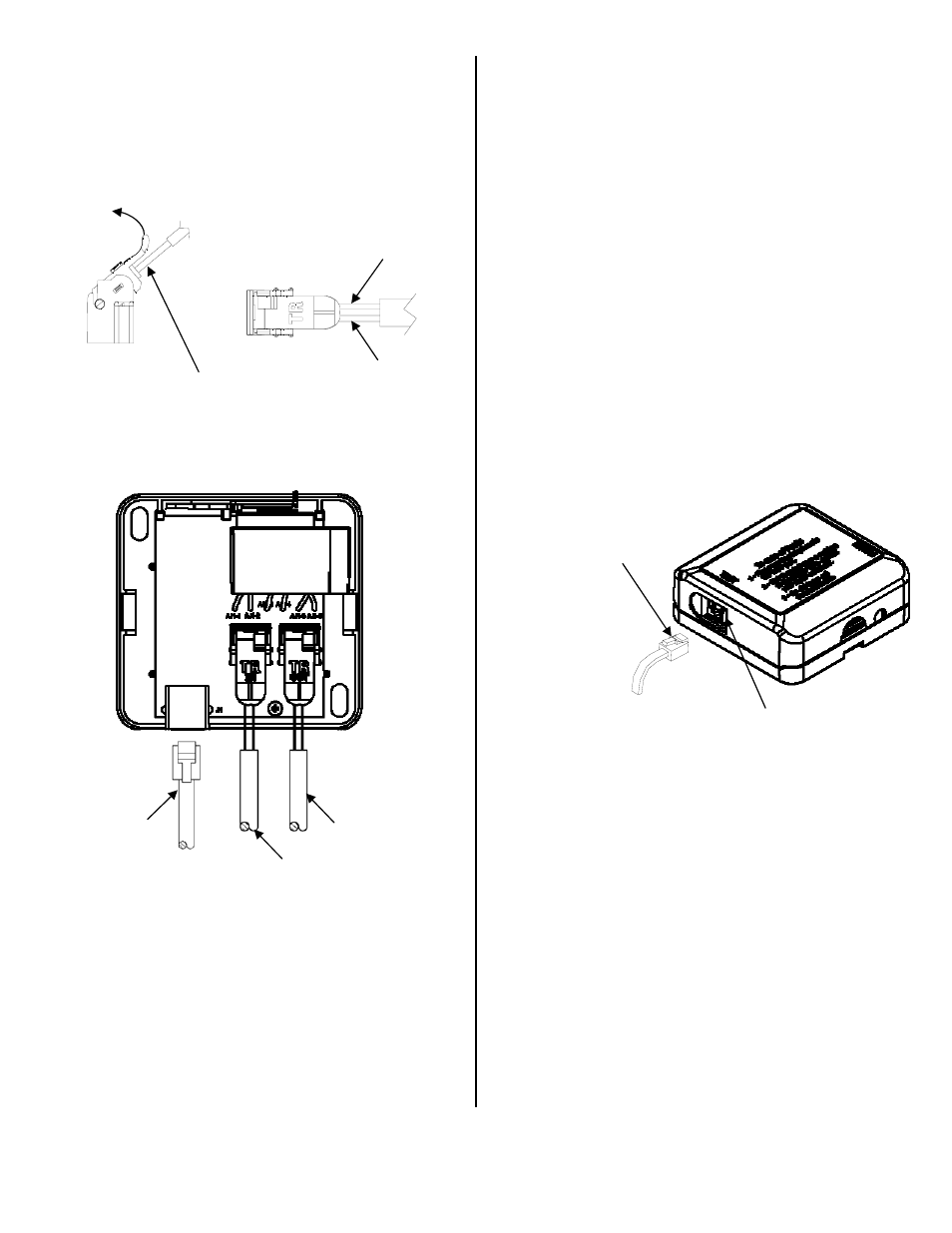
6. Push down the IDC rocker to the closed
position for termination. See Figure 2 for the
TII 751-1T-01 wiring.
7. If the customer premise wiring is fitted with an
RJ11 connector (See Figure 2), you may use
the RJ11 jack in place of the IDC (marked
“OUT) as mentioned in step 7.
Figure 1
Figure 2
Final Installation Step
1. Fasten the TII 751-1T-01 to the wall using the
(2) #8 screws provided.
2. Trim out the wires holes required in the top
cover to allow the wires to exit the unit.
3. Snap the top cover onto the base making sure
the wires do not get pinched between them.
Central Office Signal Testing
1. Slide open the cover from the Auto-Jack
®
test
receptacle located on the side of unit. Using a
working telephone, insert the telephone RJ-11
plug into the Auto-Jack (See Figure 3).
2. Wait a few seconds, lift the receiver and listen
for a dial tone.
3. If dial tone is not present, check connection to
the service wires from the telephone company.
Once the connections are verified and dial
tone is still not detected, contact the phone
service provider.
4. If the dial tone is present, then the phone line
service up to the Baseboard Jack is functional.
Remove the telephone plug from the test jack
and close the sliding cover.
5. Check for dial tone on all other telephones
within the premises. If the dial tone is audible,
the proper connections have been made.
Figure 3
RJ11 PLUG FROM GOOD
WORKING TELEPHONE
SLIDING DOOR
TELCO SERVICE
WIRE CONNECTIONS
CUSTOMER WIRING
TO PREMISES
OPTIONAL RJII
CUSTOMER WIRING
TO PREMISES
RED WIRE
(RING)
GREEN WIRE
(TIP)
DO NOT STRIP WIRES
THEN FULLY INSERT
WIRES INTO ROCKER
PULL UP
ROCKER