Tii 751-1T-01 User Manual
Tii Equipment
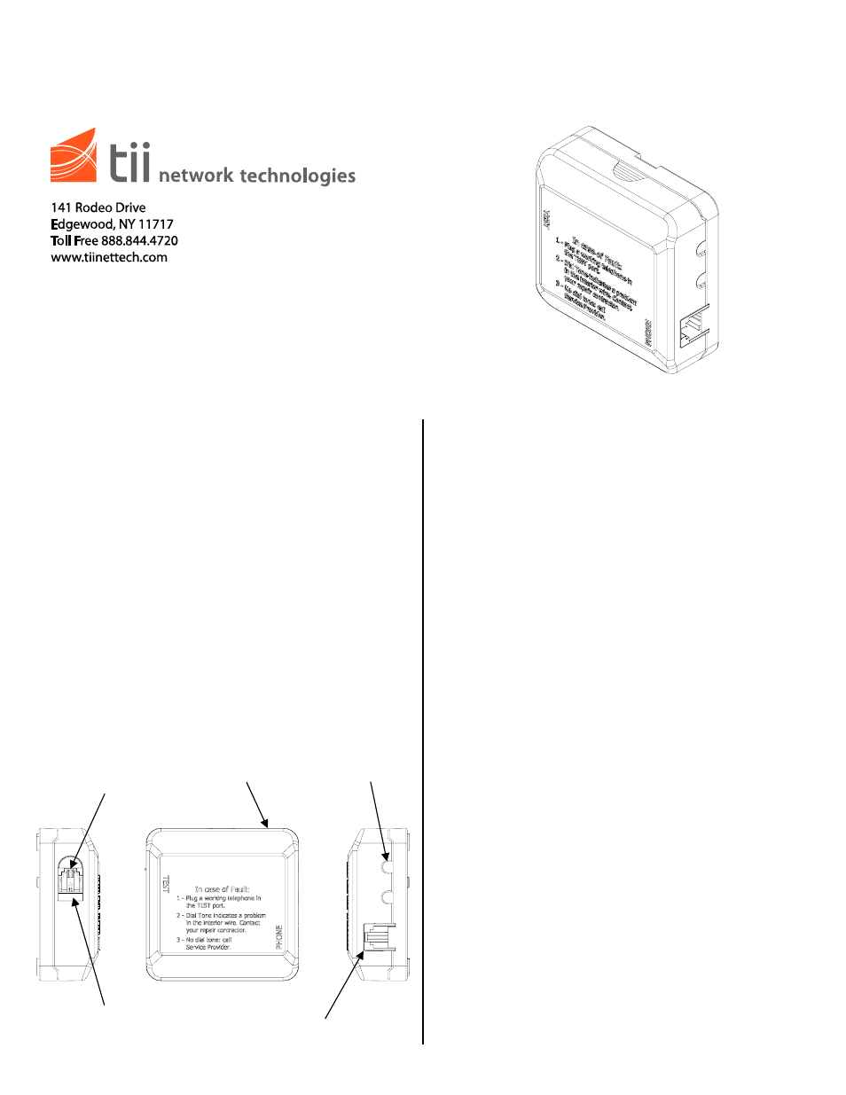
RJ11 OUTPUT
CONNECTOR
AUTOJACK
SLIDER
DOOR
REMOVABLE TOP
COVER TO ACCESS
IDC CONNECTIONS
UNTRIMMED WIRING
EXITING HOLES
P/N 92233501 • Rev B• 11/23/2009
Warranty: If this unit fails during the warranty period, contact tii customer service to authorize return. Unit may be returned prepaid.
Model 751-1T-01
Indoor Baseboard Jack
Installation Note
Description
1. The TII 751-1T-01 is an Indoor Network
demarcation point device suitable for multi
dwelling units. When installed at the service
entry point phone outlet, the unit provides
access to the telephone company’s central
office signals while disconnecting the inside
premises wiring. This is accomplished by
accessing the test jack identified on the front
of each unit. A “full-time” phone jack is also
provided on each unit so that a telephone
connection may be established at the location.
The unit is equipped with a half-ringer test
circuit for remote testing.
2. The TII 751-1T-01 is a surface mount unit
which may be mounted to a wall surface.
Features
Installation
General Notice:
1. Installation of the TII 751-1T-01 must be in
accordance with the local Codes and Article
800 of the National Electric Code, ANSI/NFPA
70.
2. The TII 751-1T-01 is intended for indoor use.
3. In a typical installation the TII 751-1T-01 is
installed ahead of all telephone connections
inside the customer premises. The unit must
be installed at the point of service wire entry.
All customer premises wiring is then fed from
the TII 751-1T-01 Baseboard Jack.
Installing the Baseboard Jack:
1. Detach the cover from the base by depressing
the finger grips located on both sides of the
cover. Pull the cover away from the base.
2. Identify and isolate the incoming telephone
company wires from the customer premises
wiring.
3. Install the tip and ring wires from the
telephone company into the IDC rocker
(marked “IN”). Do not strip the wires. Pull up
the IDC rocker to the fully open position &
insert the Telco wires until they bottom out
(See Figure 1).
4. Push down the IDC rocker to the closed
position for termination. See Figure 2 for the
TII 751-1T-01 wiring.
5. Install the inside customer premises wiring into
the IDC rocker (marked “OUT”). Do not strip
the wires. Pull up the IDC rocker to the fully
open position & insert the customer premise
wires until they bottom out (See Figure 1).