Flow meter assembly, Kit assembly, Flow meter assembly kit assembly – TeeJet Sentry 6140 User Manual
Page 9: Sentry 6140 tip flow monitor, Flow meter gasket, Towards flow meter, Flow meter nozzle body nozzle body end cap, Sensor clips, Tip sensor interface slots
7
98-05306-ENUS R2
Sentry 6140 Tip Flow Monitor
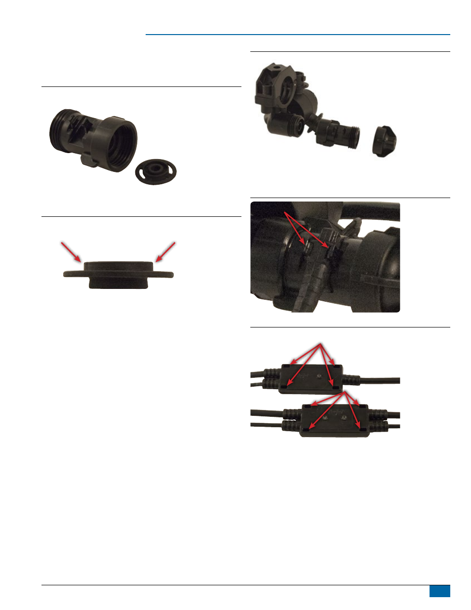
Flow Meter Assembly
The flow meter gasket has two different sides. The side with the larger
center is to be inserted towards the sensor or inside the flow meter.
Figure 5: Flow Meter and Gasket
Flow Meter
Gasket
Figure 6: Gasket Detail
towards
flow meter
Kit Assembly
1. Remove end cap from nozzle body.
2. Attach end cap to flow meter
(J)
.
3. Attach flow meter to nozzle body. Hand tighten.
4. Loosely secure Tip Sensor Interface
(H or I)
close to nozzle body
/ flow meter assembly. Cable ties (not included) can be threaded
through Tip Sensor Interface slots.
5. Push sensor of Tip Sensor Interface into slot on flowmeter. Clips on
flow meter should be in the groves on the center of the sensor.
6. Secure Tip Sensor Interface.
7. Connect Start Terminator
(L)
to section 1 Tip Sensor Interface.
8. Connect each Tip Sensor Interface moving from left to right (while
standing at the back of the machine).
►Extension cables from Boom Interface Module Harness
(E)
and
Tip Flow Monitor Interface Harness
(C)
will connect between
two Tip Sensor Interfaces.
9. Connect End Terminator
(K)
to the last section’s Tip Sensor
Interface.
Figure 7: Nozzle Body with Flow Meter Assembly
Flow Meter
nozzle Body
nozzle Body
end Cap
Figure 8: Sensor & Clips
Sensor
Clips
Figure 9: Tip Sensor Interface Slots
tip Sensor interface slots