Power, Power 8, Tip flow monitor – TeeJet Sentry 6140 User Manual
Page 10: Sentry 6140
8
www.teejet.com
Sentry 6140
Tip Flow Monitor
power
Slide the POWER SWITCH to power on or off the console.
On power up the console detects the number of Tip Sensor
Interfaces (TSI)
(H or I)
on the boom and displays the status of the
sensors and the system. The LED’s on each TSI are turned on and go
off as each is detected and given their unique address.
The addresses start at #1 and continue across the boom. Tips
are numbered from left to right while standing in the forward facing
direction of the machine and begin at the Start Terminator.
►Sensor connected to the Start Terminator [female]
(L)
on the left
side of the machine will be #1
►Sensor connected to the End Terminator [male]
(K)
on the right
side of the machine will be the last sensor.
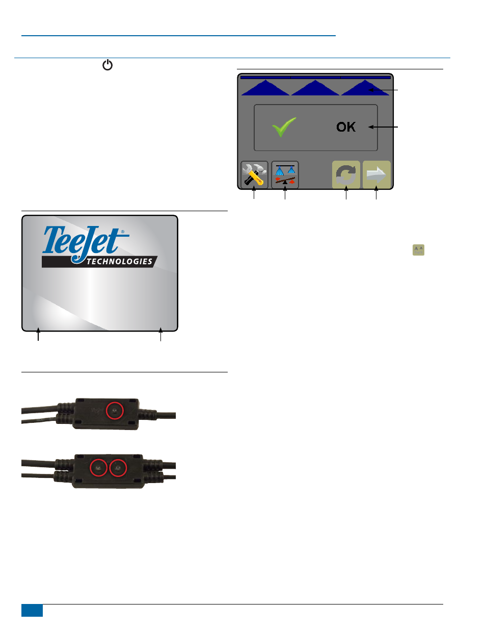
The Status Box displays if all tips are OK or if any errors are found.
Figure 10: Splash Screen
Sentry 6140
Tip Flow Monitor
Test-v1.00h
©2012
TFMI V1.00g
TFIM Software
Version
Console Software
Version
Figure 11: Tip Sensor Interface LEDs
Single tip Sensor interface
Dual tip Sensor interface
Figure 12: Home Screen
Reset
Status Box
Boom Status
Tip Balance
Next Error
Setup
NOTE: Screen options may vary depending on enabled or disabled
functions as well as function availability.
The Balance button will be unavailable or grayed out
if all
boom sections and the master switch are not on.